Compensating for effects of topography variation by using a variable intensity-threshold

a technology of topography variation and intensity threshold, applied in the field of integrated circuit fabrication, can solve the problems of variation in the critical dimension (cd) of printed patterns, the actual characteristics of integrated circuits to be different from the desired characteristics, and the defocus of aerial images, so as to accurately determine the critical dimension of features

Active Publication Date: 2007-04-12
SYNOPSYS INC
View PDF1 Cites 12 Cited by
  • Summary
  • Abstract
  • Description
  • Claims
  • Application Information

AI Technical Summary

Benefits of technology

[0017] Another embodiment of the present invention provides a system that accurately determines a critical dimension of a feature in a layout by compensating for the effects of topography variation on the performance of one or more semiconductor manufacturing processes. During operation, the system first receives a layout. Next, the system computes a process indicator at an evaluation point in the layout using a process model that models the one or more semiconductor manufacturing processes. Note, the system can compute the process indicator by convolving the process model with the ...

Problems solved by technology

Since it is almost impossible to perfectly control these complex physical and chemical interactions, these processes typically have process variations that can cause the characteristics of the actual integrated circuit to be different from the desired characteristics.
Topography variation on the wafer surface can cause portions of the wafer's surface to be above or below the focal place, which can result in the aerial-i...

Method used


Image

  • Compensating for effects of topography variation by using a variable intensity-threshold
  • Compensating for effects of topography variation by using a variable intensity-threshold
  • Compensating for effects of topography variation by using a variable intensity-threshold

Examples


Embodiment Construction

Integrated Circuit Design Flow

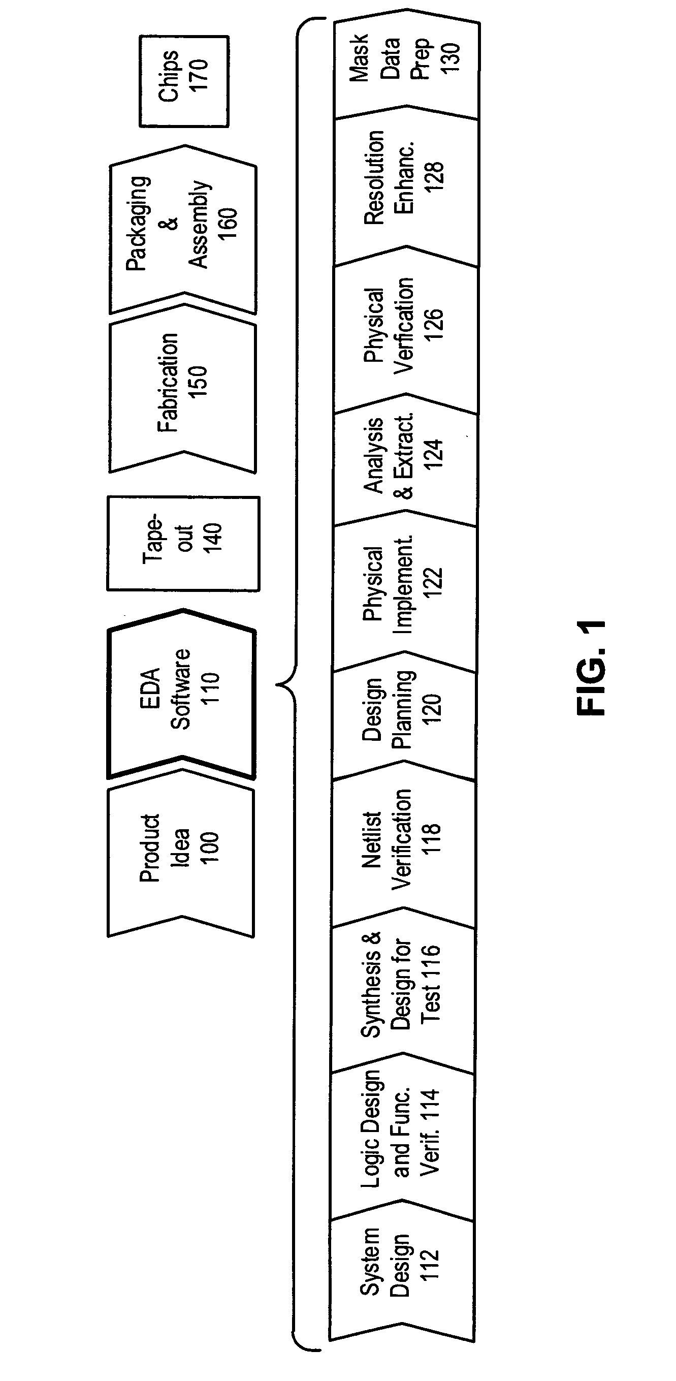
[0025]FIG. 1 illustrates an exemplary integrated circuit design flow in accordance with an embodiment of the present invention.

[0026] The process starts with the product idea (step 100) which is realized using an EDA software design process (step 110). When the design is finalized, it can be taped-out (event 140). After tape out, the fabrication process (step 150) and packaging and assembly processes (step 160) are performed which ultimately result in finished chips (result 170).

[0027] The EDA software design process (step 110), in turn, comprises steps 112-130, which are described below. Note that the design flow description is for illustration purposes only. Specifically, this description is not meant to limit the present invention. For example, an actual integrated circuit design may require the designer to perform the design steps in a different sequence than the sequence described below. The following text provides a brief description of the st...


PUM


Abstract

One embodiment of the present invention provides a system that accurately determines a critical dimension of a feature in a layout by compensating for the effects of topography variation on the performance of an optical lithography process. During operation, the system first receives a layout. Next, the system computes an aerial-image intensity at an evaluation point in the layout using an optical lithography model that models the optical lithography process. Note that the aerial-image intensity is typically compared with a constant intensity threshold to determine a critical dimension of a feature in the layout. The system then computes an intensity threshold based on features in the proximity of the evaluation point, which compensates for the effects of topography variations on the performance of the optical lithography process. Next, the system determines the critical dimension of the feature by comparing the aerial-image intensity with the computed intensity threshold, instead of comparing the aerial-image intensity with the constant intensity threshold.

Description

BACKGROUND [0001] 1. Field of the Invention [0002] The present invention relates to integrated circuit fabrication. More specifically, the present invention relates to a method and apparatus for compensating for effects of topography variation by using a variable intensity-threshold during an OPC process. [0003] 2. Related Art [0004] Dramatic improvements in semiconductor integration circuit (IC) technology presently make it possible to integrate tens of millions of transistors, onto a single semiconductor IC chip. These improvements in integration densities have been achieved through corresponding improvements in semiconductor manufacturing technologies. In particular, advances in optical lithography technology have been driving IC chip feature sizes into deep-submicron ranges, with the help of Optical Proximity Correction (OPC) techniques. [0005] Semiconductor manufacturing technologies typically include a number of processes which involve complex physical and chemical interaction...

Claims


Application Information

Patent Timeline
IPC IPC(8): G03C5/00G06K9/00
CPCG06F17/5081G06F2217/12G06F30/398G06F2119/18Y02P90/02
Inventor MELVIN, LAWRENCE S. IIIHUANG, JENSHENG
Owner SYNOPSYS INC
Why Eureka
Try Eureka