Ultrasonic fault detection system using a high dynamic range analog to digital conversion system

Inactive Publication Date: 2007-04-19
OLYMPUS NDT
View PDF16 Cites 61 Cited by
  • Summary
  • Abstract
  • Description
  • Claims
  • Application Information

AI Technical Summary

Benefits of technology

[0016] Another aspect of the invention includes: a means to adjust the respective sample times to compensate for all sources of timing skew, including the propagation delays of each preamplifier and any other source of skew revealed by examination of the A/D converter output data; a means for preventing saturation of the input stage of each channel's preamplifier to prevent signal distortion from affecting the inputs to the other channels; a means for adjusting the frequency response of each channel to substantially match, as well

Problems solved by technology

In general, prior art ultrasonic flaw detectors utilize highly complex analog front ends that contain many parts which pose especially difficult problems in terms of calibration, reliability, set up time, consistency of results and optimization for specific usages and settings.
As a result, present flaw detectors present a host of problems to designers and users of such equipment, which impact their troubleshooting and repair owing to their complexity.
These problems include such issues as matching input impedances seen by the transducer which changes with different gain amplifiers that are switched in and out of the signal path.
This adversely impacts the frequency response and introduces various gain nonlinearities.
It poses issues of calibration, as analog circuits are switched in and out of the signal path.
Another problem with existing flaw detectors is attributable to their back wall attenuation performance which impacts the ability to detect flaws that are located very near the back wall of the object being tested.
This problem poses particular problems with the time varied gain function which has a limited g

Method used


Image

  • Ultrasonic fault detection system using a high dynamic range analog to digital conversion system
  • Ultrasonic fault detection system using a high dynamic range analog to digital conversion system
  • Ultrasonic fault detection system using a high dynamic range analog to digital conversion system

Examples


Embodiment Construction

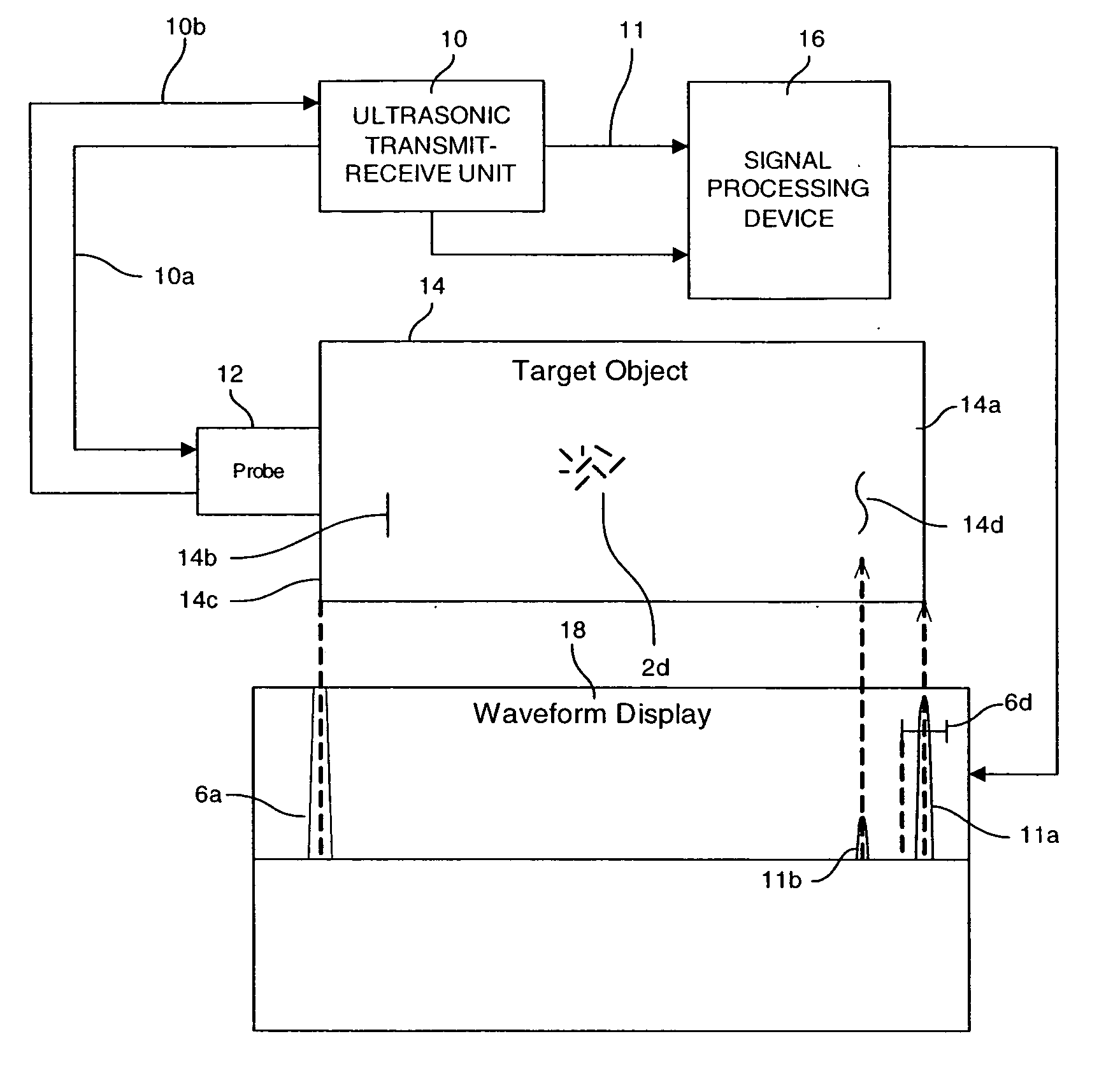
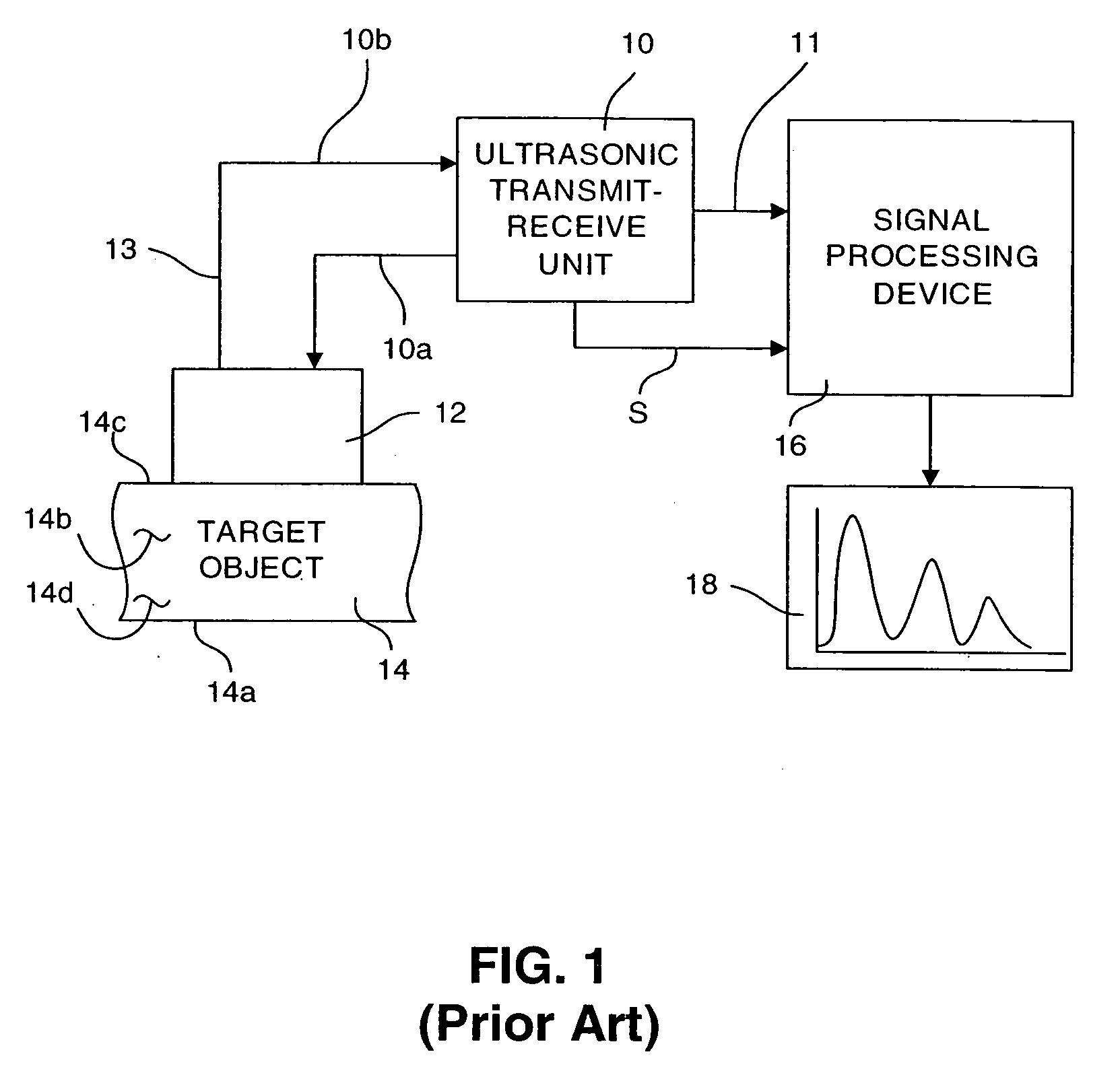
[0043] Reference is initially made to FIGS. 1 and 2, to provide background information on the general environment of and various problems solved by the present invention.

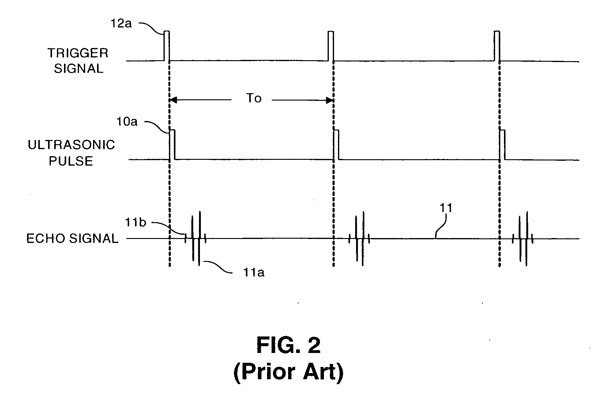
[0044] In FIG. 1, an ultrasonic transmit-receive unit 10 transmits an electrical pulse signal 10a at a predetermined period to a probe or transducer 12 which is coupled to a target object 14, such as to steel material, directly or through a delay material such as water or quartz. As shown in FIG. 2, the probe 12 converts the trigger pulse signal 12a into an ultrasonic pulse 10a which it transmits through the target object 14. The ultrasonic pulse 10a applied into the target object 14 is subsequently reflected by a bottom surface 14a of the target object 14 and received by the probe 12. The probe 12 converts the reflected wave into an electrical signal which is supplied as an electrical echo signal 10b to the ultrasonic transmit-receive unit 10. The ultrasonic transmit-receive unit 10 amplifies the electrical signal...


PUM


Abstract

A method and apparatus for effecting ultrasonic flaw detection of an object processes an echo signal received from the object being tested in at least three signal channels, wherein the echo signal is scaled to different degrees along each channel to increase and extend the dynamic range of an associated A/D converter system, in a manner which dispenses with the need for using numerous analog high pass and low pass filters and a variable gain amplifier. This reduces complexity and avoids performance limitations. The digital to analog converters sample the differently scaled input signal and a selection circuit selects the output of the digital output obtained from that analog to digital converter which has the highest gain, but which has not overflowed. The digital outputs are seamlessly merged to produce an output that can be displayed as a scan display which shows the location of faults.

Description

CROSS-REFERENCE TO RELATED APPLICATIONS [0001] This application claims the benefit and priority of U.S. Provisional patent application Ser. No. 60 / 726,798 filed Oct. 14, 2005 entitled ULTRASONIC FAULT DETECTION SYSTEM USING A HIGH DYNAMIC RANGE ANALOG TO DIGITAL CONVERSION SYSTEM and U.S. Provisional patent application Ser. No. 60 / 726,776, filed Oct. 14, 2005 entitled ULTRASONIC DETECTION MEASUREMENT SYSTEM USING A TUNABLE DIGITAL FILTER WITH 4X INTERPOLATOR, and U.S. Provisional patent application Ser. No. 60 / 726,575, filed Oct. 14, 2005 entitled DIGITAL TIME VARIABLE AMPLIFIER FOR NON-DETRUCTIVE TEST INSTRUMENT, the entire disclosures of which are incorporated herein by reference.BACKGROUND OF THE INVENTION [0002] The present invention generally relates to ultrasonic inspection systems utilized to detect internal structural faults, e.g. cracks, discontinuities, corrosion or thickness variations within an object or a material, for example, in such crucial structures as airline wing...

Claims


Application Information

Patent Timeline
IPC IPC(8): G01N29/00
CPCG01N29/043G01N29/262G01N29/42H03M1/188G01N29/4463G01N2291/044G01N2291/102G01N29/44
Inventor THOMAS, ANDREW
Owner OLYMPUS NDT
Why Eureka
Try Eureka