
Ring oscillator row circuit for evaluating memory cell performance

a memory cell and oscillator row technology, applied in the field of memory circuits, can solve the problems of critical limitations of memory speed and other performance factors, predicted to become even more critical limitations, and the difficulty of measuring the operating performance of memory cells in the presence of actual loading conditions, and achieve the effect of reducing the risk of leakag

Active Publication Date: 2007-04-19
MARVELL ASIA PTE LTD
View PDF15 Cites 25 Cited by
  • Summary
  • Abstract
  • Description
  • Claims
  • Application Information

AI Technical Summary

Benefits of technology

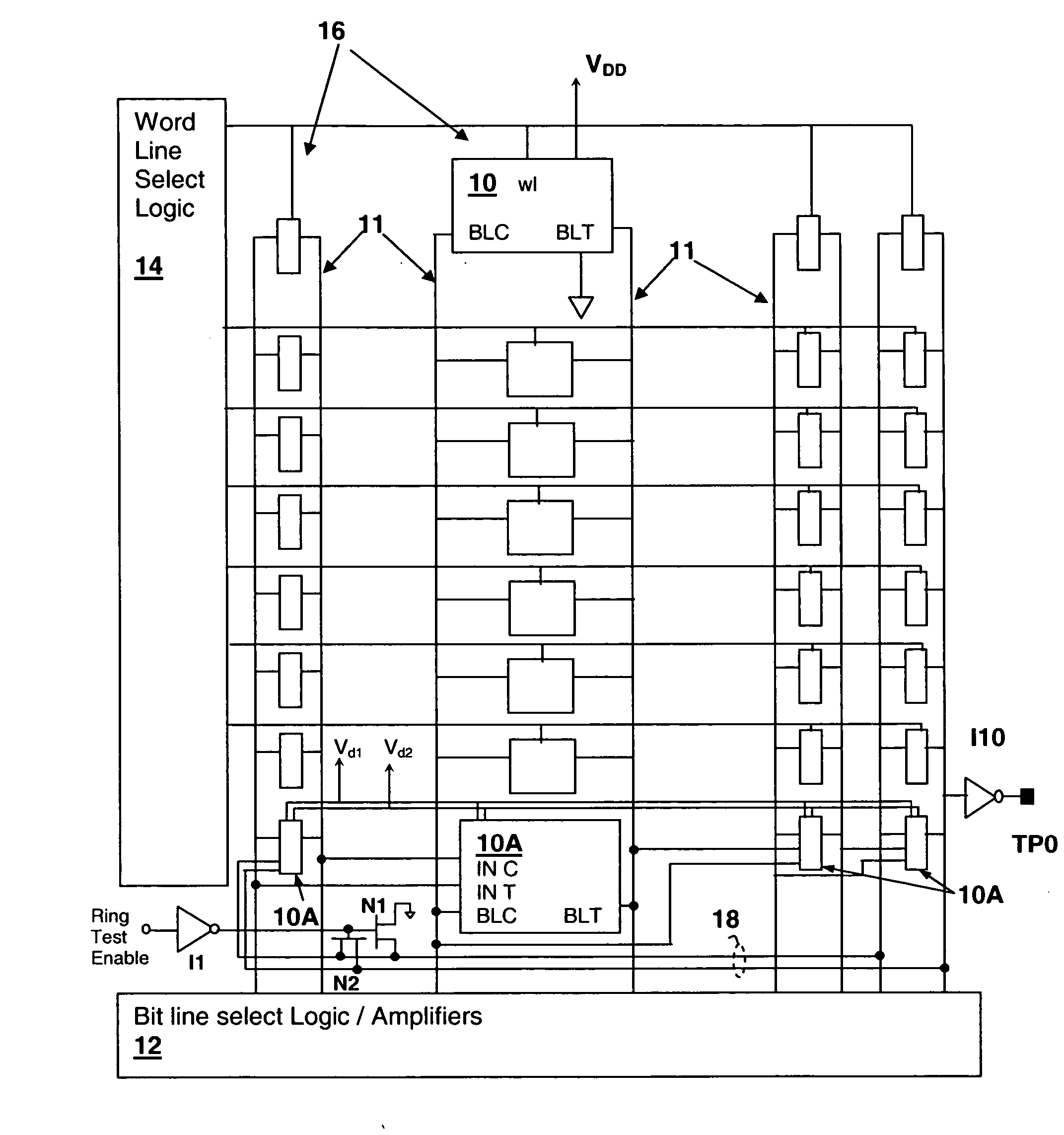
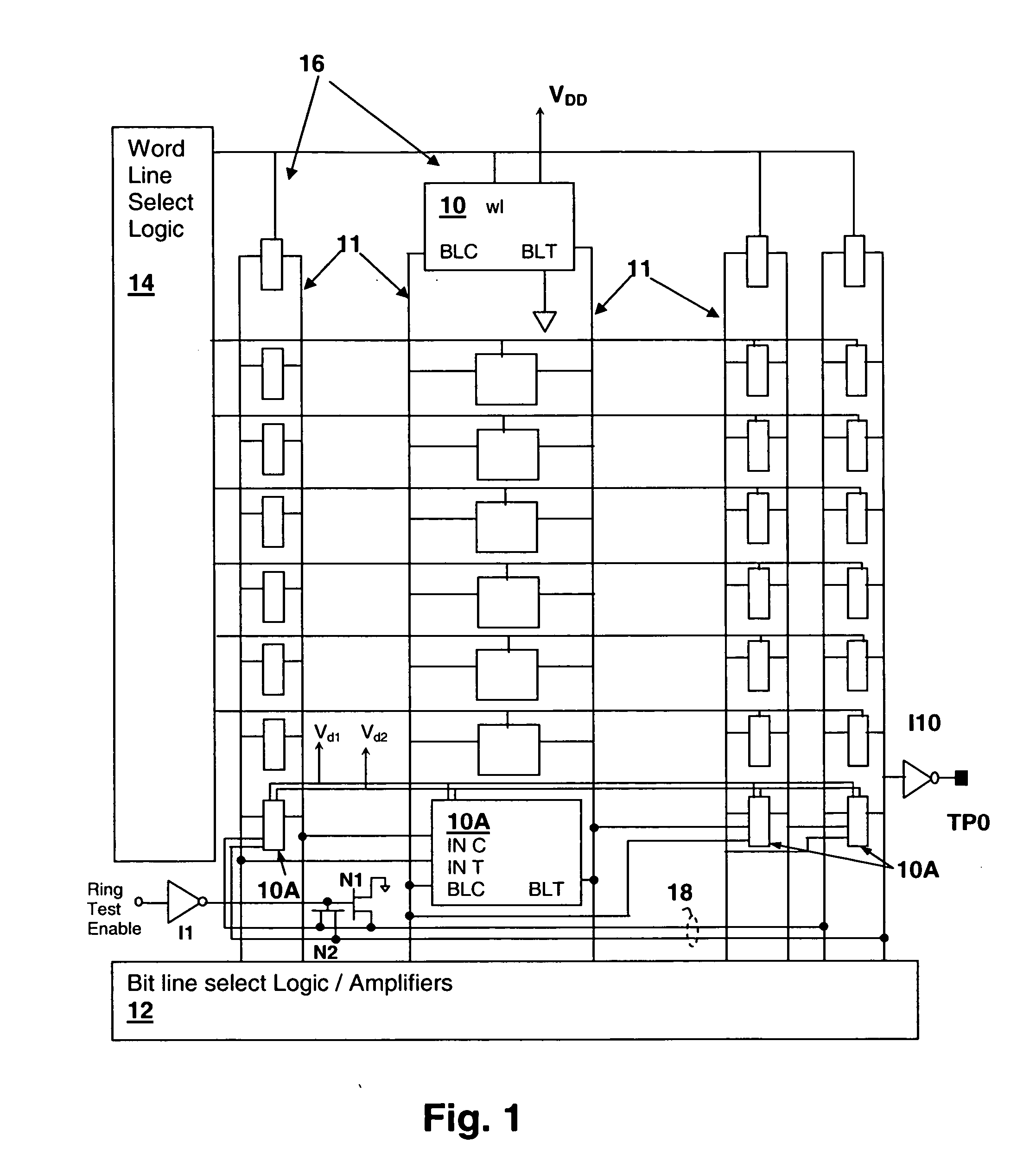
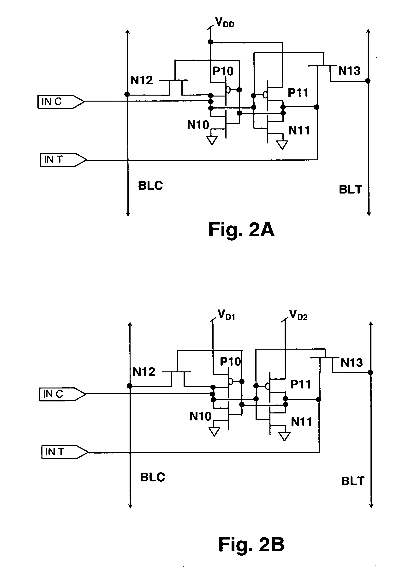
[0012] The circuit is a memory array that incorporates a ring oscillator of memory cells within a row of the array. The number of stages of the ring oscillator is generally equal to the number of cells within a row. Each stage of the ring oscillator is connected to the memory array just as a standard member of the corresponding column, i.e., each cell has its input / output connections coupled to bitlines of a corresponding column. The circuit under test may be a 6 transistor static random access memory SRAM cell with a pair of cross-coupled back-to-back complementary transistor inverters and with a series word / bit-line transmission control transistor between the output of each inverter and the corresponding word / bit-line or the cell may be a different design or different type of memory cell.
[0013] An asymmetry may be introduced in one or more of the ring oscillator cells, which may be a different power supply voltage supplied to each of a pair of inverters implementing the cell. Effects of leakage on delay be measured by adjusting the values of the other memory cells via a test method that studies changes in the ring oscillator frequency as the states of the other cells are varied.

Problems solved by technology

Memory speed and other performance factors are critical limitations in today's processing systems and are predicted to become even more of a critical limitation as technologies move forward.
However, measuring operating performance of memory cells in the presence of actual loading conditions presents a challenge.
However, present ring oscillator circuits and tests typically either are not applied on production dies or they do not test the memory cells under loading conditions identical to placement of the cells within an actual memory array.

Method used


Image

  • Ring oscillator row circuit for evaluating memory cell performance
  • Ring oscillator row circuit for evaluating memory cell performance
  • Ring oscillator row circuit for evaluating memory cell performance

Examples


Embodiment Construction

[0023] The present invention concerns a ring oscillator circuit for evaluating performance of memory cells and memory arrays in order to facilitate design improvement and determination of operating margins. In particular, a ring oscillator is implemented in a row of a memory array, which may be a production memory array tested for ongoing product analysis or a test memory array implemented and tested for laboratory analysis. The oscillator row is connected within a memory array just as other rows: the input / output connections of the memory cells in the oscillator row are connected to their corresponding column bitlines. One or more internal nodes of each of the ring oscillator cells may be connected to previous bitline(s) to propagate a logic state change from the previous bitline(s) through the cell to the output bitline(s). The passgates have enable inputs connected to the outputs of the opposite internal state output of the cell, so that when the state of one of the inverter outp...


PUM


Abstract

A ring oscillator row circuit for evaluating memory cell performance provides for circuit delay and performance measurements in an actual memory circuit environment. A ring oscillator is implemented with a row of memory cells and has outputs connected to one or more bitlines along with other memory cells that are substantially identical to the ring oscillator cells. Logic may be included for providing a fully functional memory array, so that the cells other than the ring oscillator cells can be used for storage when the ring oscillator row wordlines are disabled. One or both power supply rails of individual cross-coupled inverter stages forming static memory cells used in the ring oscillator circuit may be isolated from each other in order to introduce a voltage asymmetry so that circuit asymmetry effects on delay can be evaluated.

Description

CROSS-REFERENCE TO RELATED APPLICATION [0001] The present application is related to co-pending U.S. patent application “METHODS AND CIRCUITS FOR EVALUATING STATIC MEMORY CELL DYNAMIC STABILITY”, Ser. No. 11 / ___,___, Attorney Docket No. AUS920050345US1, filed on ______ and “BITLINE VARIABLE METHODS AND CIRCUITS FOR EVALUATING STATIC MEMORY CELL DYNAMIC STABILITY”, Ser. No. 11___,___, Attorney Docket No. AUS920050625US1, the applications having at least one common inventor with the present application and are assigned to the same Assignee. The entire disclosures of the above-referenced applications are incorporated herein by reference. [0002] The present application is also related to U.S. Patent Application “CASCADED TEST CIRCUIT WITH INTER-BITLINE DRIVE DEVICES FOR EVALUATING MEMORY CELL PERFORMANCE”, Ser. No. 11 / ___,___, Attorney Docket No. AUS920050460US1, filed concurrently herewith and assigned to the same Assignee.BACKGROUND OF THE INVENTION [0003] 1. Technical Field [0004] The...

Claims


Application Information

Patent Timeline
Patent Type & Authority Applications(United States)
IPC IPC(8): G11C11/00
CPCG11C29/50G11C29/50012
Inventor JOSHI, RAJIV V.YE, QIUYICHAN, YUEN H.DEVGAN, ANIRUDH
Owner MARVELL ASIA PTE LTD
Learn More