Control device for vehicular drive system, vehicle having the control device, and method for controlling vehicular drive system

a control device and vehicular drive technology, applied in the direction of electric propulsion mounting, transportation and packaging, gearing, etc., can solve the problems of not having any power transmission mechanism having the advantages, and the vehicular drive system suffering from a similar problem, so as to improve the efficiency of continuously variable shifting control of the continuously variable transmission portion, compact in size, and compact in size

Inactive Publication Date: 2007-04-19
TOYOTA JIDOSHA KK
View PDF2 Cites 15 Cited by
  • Summary
  • Abstract
  • Description
  • Claims
  • Application Information

AI Technical Summary

Benefits of technology

[0027] Preferably, an overall speed ratio of the vehicular drive system is defined by a speed ratio of the continuously-variable transmission portion and a speed ratio of the automatic transmission portion. In this arrangement, the vehicle drive force can be obtained over a relatively wide range of the overall speed ratio, by utilizing the speed ratio of the automatic transmission portion, so that the efficiency of the continuously-variable shifting control of the continuously-variable transmission portion is further improved. Where the second electric motor is connected to the power transmitting member, with the automatic transmission portion being operated as a speed-reducing transmission having a speed ratio larger than 1, the output torque of the second electric motor may be smaller than the output torque of the output shaft of the transmission portion, so that the second electric motor can be made compact in size. The continuously-variable transmission portion placed in the continuously-variable shifting state and the automatic transmission portion cooperate to constitute a continuously-variable transmission, and the continuously-variable transmission portion placed in the non-continuously-variable shifting state and the automatic transmission portion cooperate to constitute a step-variable transmission.
[0028] Preferably, an overall speed ratio of the vehicular drive system is defined by a speed ratio of-the differential portion and a speed

Problems solved by technology

However, there is not available any power transmitting mechanism having the advantages of those two types of transmission.
Where the above-described differential mechanism is a transmission

Method used


Image

  • Control device for vehicular drive system, vehicle having the control device, and method for controlling vehicular drive system
  • Control device for vehicular drive system, vehicle having the control device, and method for controlling vehicular drive system
  • Control device for vehicular drive system, vehicle having the control device, and method for controlling vehicular drive system

Examples


embodiment 1

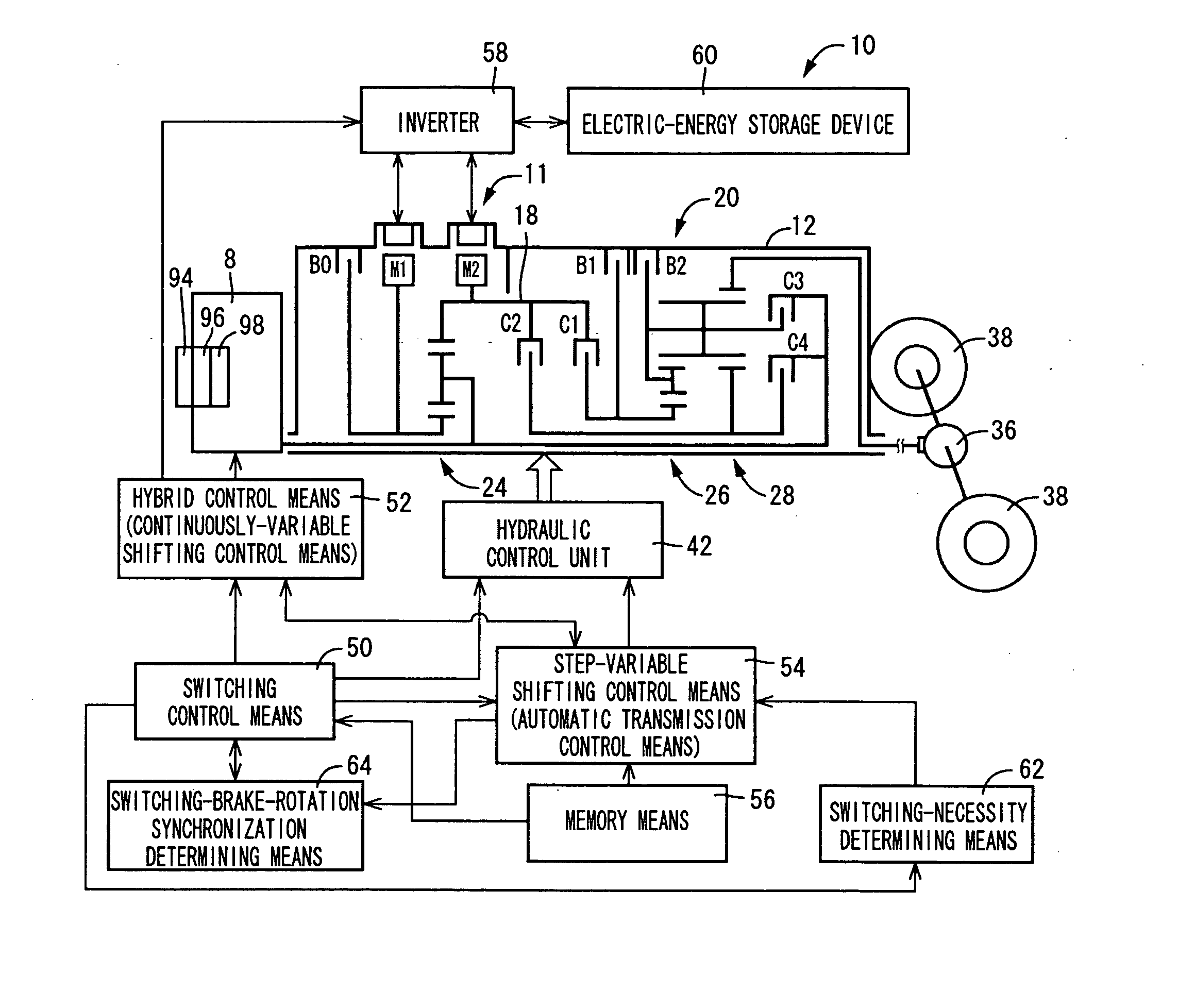
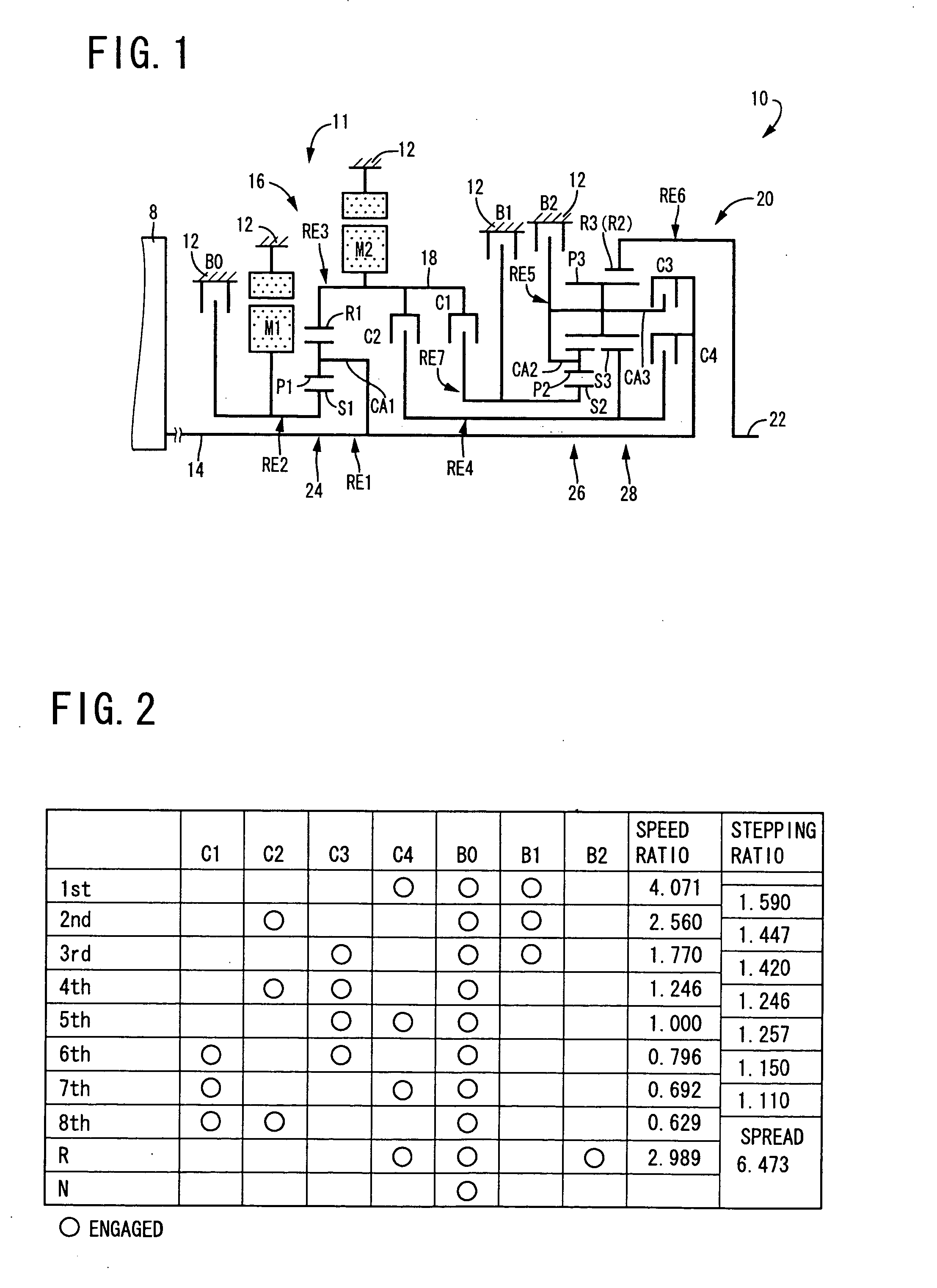
[0051] Referring to the schematic view of FIG. 1, there is shown a transmission mechanism 10 constituting a part of a drive system for a hybrid vehicle, which drive system is controlled by a control apparatus according to one embodiment of this invention. In FIG. 1, the transmission mechanism 10 includes: an input rotary member in the form of an input shaft 14; a continuously-variable transmission portion in the form of a differential portion 11 connected to the input shaft 14 either directly, or indirectly via a pulsation absorbing damper (vibration damping device) not shown; a step-variable or multiple-step transmission portion in the form of an automatic transmission portion 20 disposed between the differential portion 11 and drive wheels 38 of the vehicle, and connected in series via a power transmitting member 18 (power transmitting shaft) as an output rotary member of the differential portion 11, to the differential portion 11 and the drive wheels 38; and an output rotary memb...

embodiment 2

[0155]FIG. 15, which corresponds to FIG. 1, is a schematic view for explaining a construction of a transmission mechanism 70 in another embodiment of this invention. FIG. 16, which corresponds to FIG. 2, is a table indicating a relationship between the gear positions of the transmission mechanism 70 and different combinations of engaged states of the hydraulically operated frictional coupling devices for respectively establishing those gear positions, while the transmission mechanism 70 is operated as a step-variable transmission. FIG. 17, which corresponds to FIG. 3, is a collinear chart for explaining relative rotational speeds of the elements in each gear position while the transmission mechanism 70 is operated as the step-variable transmission. FIG. 18, which corresponds to FIG. 4, is a table indicating a relationship between the gear positions of the transmission mechanism 70 and different combinations of engaged states of the hydraulically operated frictional coupling devices ...


PUM


Abstract

A control apparatus for a vehicular drive system including a first transmission portion having a differential mechanism operable to distribute an engine output to a first electric motor and a power transmitting member, and a second electric motor disposed in a power transmitting path between the power transmitting member and a drive wheel; and a second transmission portion constituting a part of the power transmitting path. The control apparatus includes a switching device provided in the differential mechanism and operable to selectively place the first transmission portion in a continuously-variable shifting state and in a non-continuously-variable shifting state, rendering the first transmission portion respectively capable or not capable of operating as an electrically controlled continuously variable transmission; and a transmission controller operable to change a speed ratio of the second transmission portion, concurrently with switching of the first transmission portion between the continuously-variable shifting state and the non-continuously-variable shifting state.

Description

[0001] The present application is based on Japanese Patent Application No. 2005-182398. BACKGROUND OF THE INVENTION [0002] 1. Field of the Invention [0003] The present invention relates to a vehicular drive system including a differential mechanism having a differential function, and electric motors, and more particularly to techniques for reducing the size of the electric motors. [0004] 2. Discussion of Prior Art [0005] There is known a drive system for a vehicle, which includes a differential mechanism operable to distribute an output of an engine to a first electric motor and its output shaft, and a second electric motor disposed between the output shaft of the differential mechanism and a drive wheel of the vehicle. Patent Document 1 discloses an example of such a vehicular drive system, which is a hybrid vehicle drive system. In this hybrid vehicle drive system, the differential mechanism is constituted by a planetary gear set, for example, and a major portion of a drive force ...

Claims


Application Information

Patent Timeline
IPC IPC(8): B60K1/02B60K6/365B60K6/445B60K6/543B60K6/547B60K17/04B60L50/16B60W10/06B60W10/10B60W20/00F16H3/62F16H3/66F16H3/72F16H59/42F16H59/68F16H61/02F16H61/68F16H61/684F16H61/686
CPCB60K6/445B60K6/448B60W10/08B60W10/115Y10T477/23B60W30/19Y02T10/6243Y02T10/6239B60W20/00Y02T10/62B60W20/10
Inventor TABATA, ATSUSHITAGA, YUTAKAINOUE, YUJIKAMADA, ATSUSHI
Owner TOYOTA JIDOSHA KK
Why Eureka
Try Eureka