Infrared radiation element and gas sensor using it

a gas sensor and infrared radiation technology, applied in the direction of thermoelectric devices, optical radiation measurement, instruments, etc., can solve problems such as heat generator breakag

Inactive Publication Date: 2007-04-26
MATSUSHITA ELECTRIC WORKS LTD
View PDF5 Cites 10 Cited by
  • Summary
  • Abstract
  • Description
  • Claims
  • Application Information

AI Technical Summary

Benefits of technology

[0006] In view of the above problem, the object of the present invention is to provide an infrared radiation element that can have a long life, as compared with a conventional one, and a gas sensor using the infrared radiation element.

Problems solved by technology

However, in the above infrared radiation element having the micro-bridge structure, the heat generator is subject to breakage, and it may be melted by the heat because the heat generator is in the form of a line, and only both ends of the heat generator are supported by the supporting substrate.

Method used


Image

  • Infrared radiation element and gas sensor using it
  • Infrared radiation element and gas sensor using it
  • Infrared radiation element and gas sensor using it

Examples


Embodiment Construction

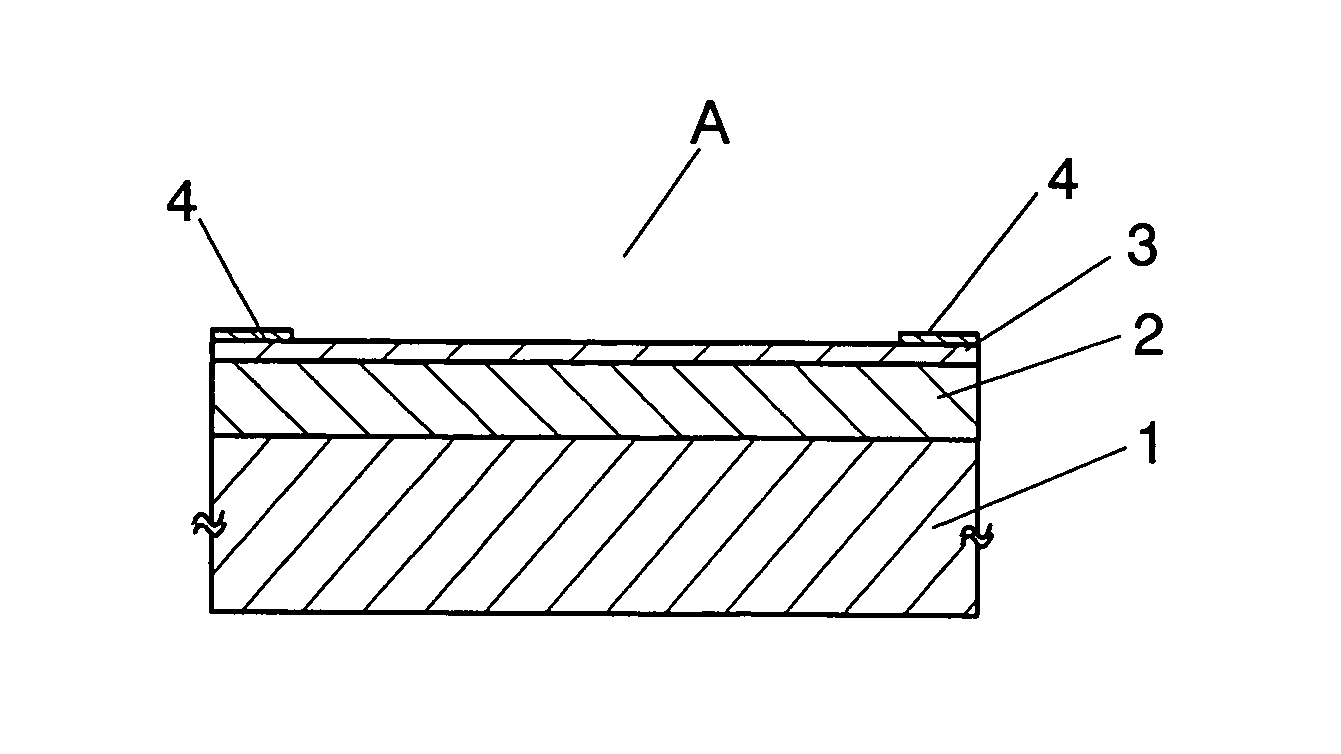
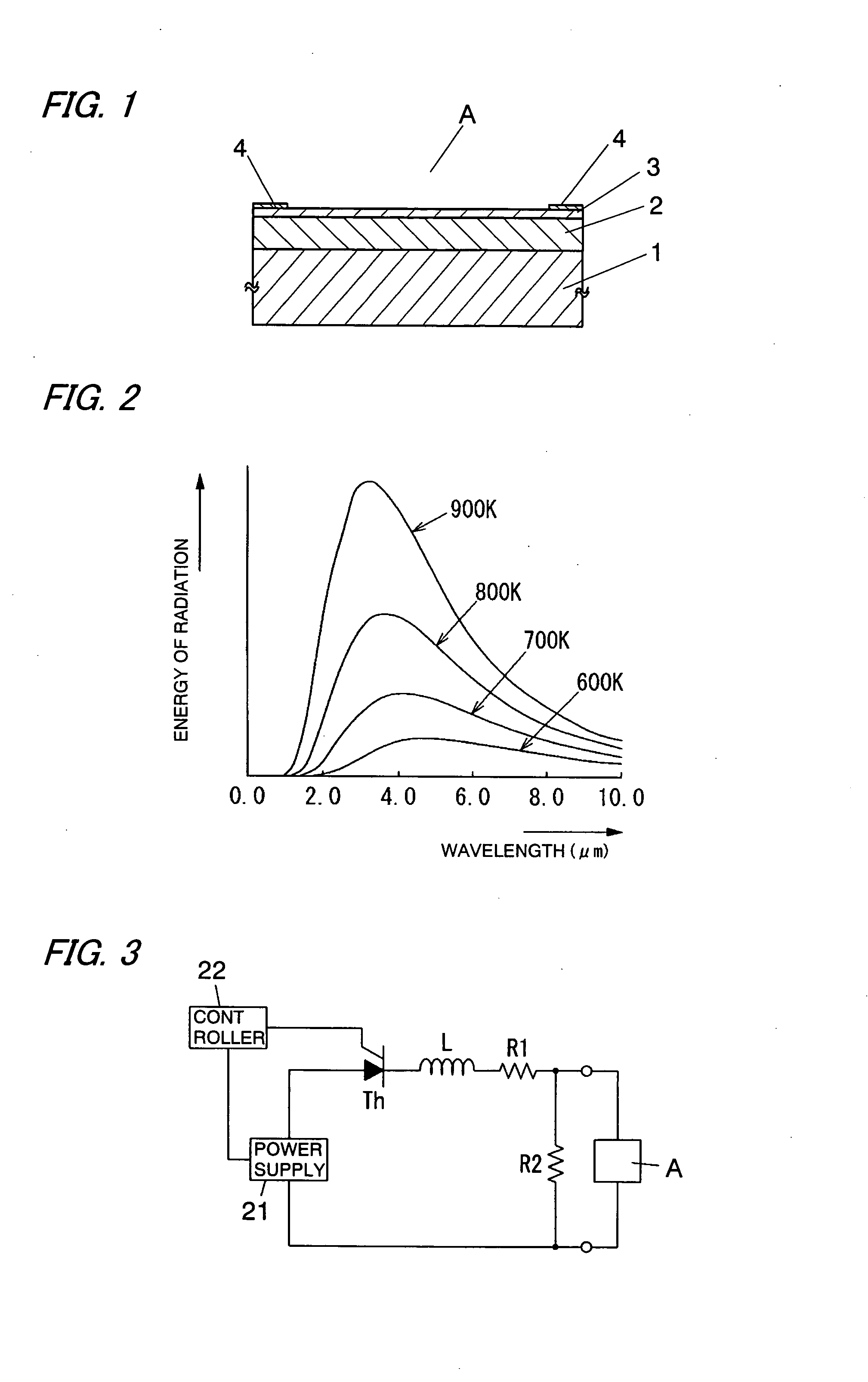
[0029] Hereinafter, an infrared radiation element (A) of the present invention will be described in more detail with reference to the accompanying drawings.

[0030] The infrared radiation element (A) of the present invention is an infrared radiation element which emits infrared rays from a heating layer 3 by heating a heating layer 3 by energization of the heating layer 3. In the infrared radiation element (A), a heat insulating layer 2, which is porous and has sufficiently smaller thermal conductivity than a semiconductor substrate 1, is formed on a surface in the thickness direction of the semiconductor substrate 1 (namely, on an upper surface of FIG. 1), and the heating layer 3, which is in the form of a lamina (a plane) and has larger thermal conductivity and larger electrical conductivity than the heat insulating layer 2, is formed on the heat insulating layer 2, and a pair of pads (electrodes) 4 for energization are formed on the heating layer 3. The semiconductor substrate 1 h...


PUM


Abstract

In the infrared radiation element (A), a heat insulating layer 2, which has sufficiently smaller thermal conductivity than a semiconductor substrate 1, is formed on a surface in the thickness direction of the semiconductor substrate 1, and a heating layer 3, which is in the form of a lamina (plane) and has larger thermal conductivity and larger electrical conductivity than the heat insulating layer 2, is formed on the heat insulating layer 2, and a pair of pads 4 for energization are formed on the heating layer 3. The semiconductor substrate 1 is made of a silicon substrate. The heat insulating layer 2 and the heating layer 3 are formed by porous silicon layers having different porosities from each other, and the heating layer 3 has smaller porosity than the heat insulating layer 2. By using the infrared radiation element (A) as an infrared radiation source of a gas sensor, it becomes possible to extend a life of the infrared radiation source.

Description

TECHNICAL FIELD [0001] The present invention relates to an infrared radiation element and a gas sensor using it. BACKGROUND ART [0002] Various kinds of analyzers that use an infrared radiation source, such as an infrared gas analyzer, have been provided. A typical infrared radiation source used in such an analyzer is a halogen lamp. However, the halogen lamp is large and has a relatively short life span, so it is difficult to apply it to a small gas sensor that detects gas using infrared rays. [0003] So, as an infrared radiation source that can be miniaturized, an infrared radiation element formed by using a micro machining technology has been developed in many places (For example, see Japanese Non-examined Patent Publication No. 9-153640 (paragraphs [0027]-[0028], FIG. 2), Japanese Non-examined Patent Publication No. 2000-236110 (paragraphs [0017]-[0019], FIGS. 1 and 2), and Japanese Non-examined Patent Publication No. 10-294165 (paragraphs [0014]-[0015], FIG. 1)). [0004] In the ab...

Claims


Application Information

Patent Timeline
Patent Type & Authority Applications(United States)
IPC IPC(8): G01J5/02H01L37/00H05B3/00H05B3/26
CPCH01L37/00H05B3/009H05B3/265H05B2203/032H10N15/00H05B3/26H01K1/04
Inventor ICHIHARA, TSUTOMUHAMADA, CHOUSEIAKEDO, KOSHIKITAMURA, HIROAKIFUKSHIMA, HIROSHIKOMODA, TAKUYAHATAI, TAKASHI
Owner MATSUSHITA ELECTRIC WORKS LTD
Why Eureka
Try Eureka