Efficient data transmission and training of data processing functions

a data transmission and data processing technology, applied in the field of optical communication networks, can solve the problems of preventing successful deployment in “real-world” installed communication networks, distorted optical signals received through conventional optical links, and significant amounts of chromatic dispersion (cd) in optical signals, and achieves cost-effective and efficient data transmission.

Inactive Publication Date: 2007-04-26
RPX CLEARINGHOUSE
View PDF27 Cites 122 Cited by
  • Summary
  • Abstract
  • Description
  • Claims
  • Application Information

AI Technical Summary

Benefits of technology

[0016] An object of the present invention is to provide methods and techniques that enable efficien

Problems solved by technology

However, receivers based on coherent detection techniques have suffered disadvantages that have, to date, prevented successful deployment in “real-world” installed communications networks.
In particular, optical signals received through conventional optical links are distorted by significant amounts of chromatic dispersion (CD) and polarization dependent impairments such as Polarization Mode Dispersion (PMD), polarization angle changes and polarization dependent loss (PDL).
These problems are compounded for polarization-division multiplexed signals, in which each transmitted polarization contains a respective different data signal.
However, Noé does not provide any teaching as to how this would be done.
A further limitation of coherent receivers is that a frequency mismatch between the received carrier and the local oscillator appears as a time varying phase error in detected symbols.
This can result in the erroneous interpretation of every symbol (and thus all data) following the cycle-slip.
However, differential decoding has a disadvantage in that a symbol error results in two errored symbols; the symbol directly affected by the symbol error

Method used


Image

  • Efficient data transmission and training of data processing functions
  • Efficient data transmission and training of data processing functions
  • Efficient data transmission and training of data processing functions

Examples


Embodiment Construction

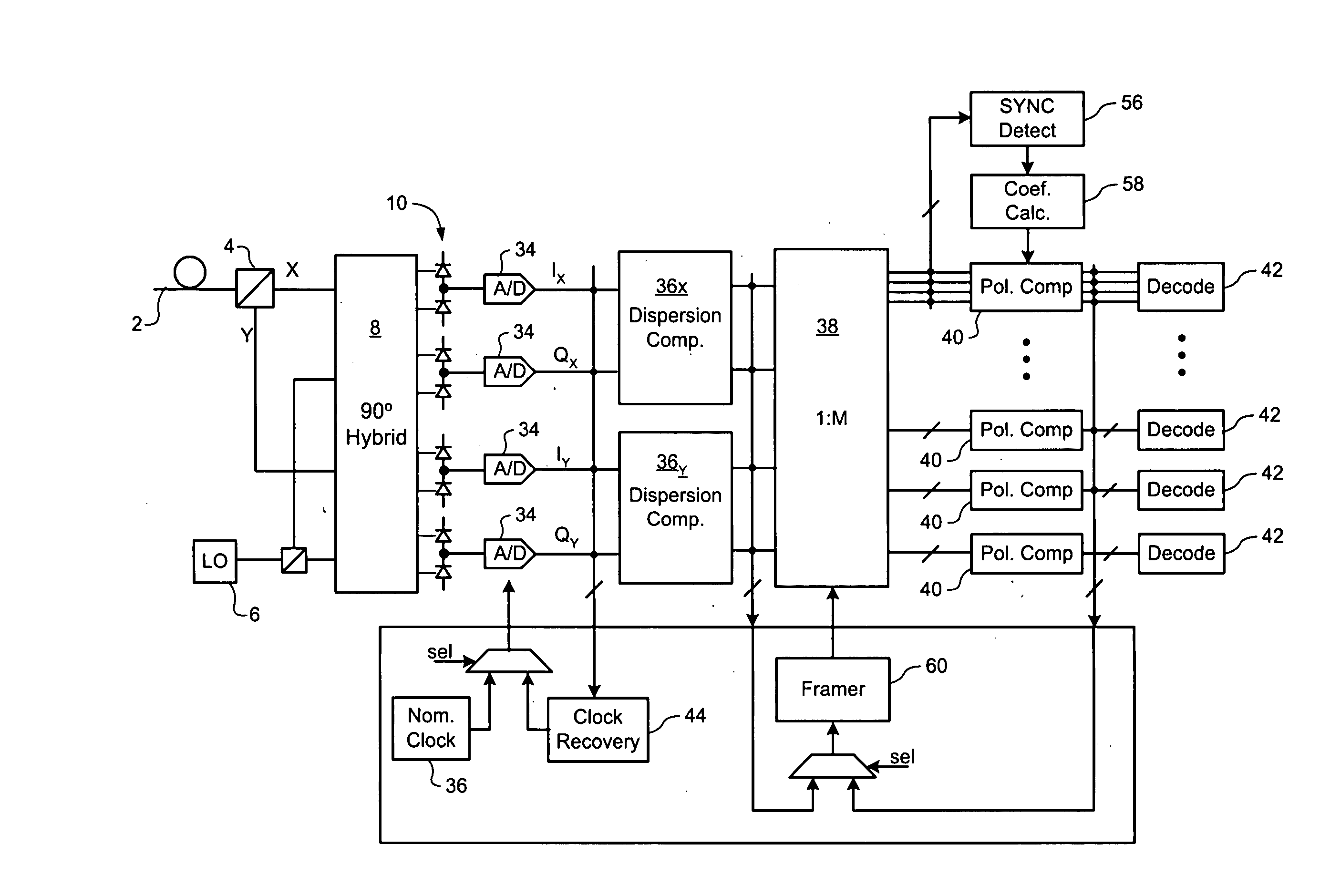
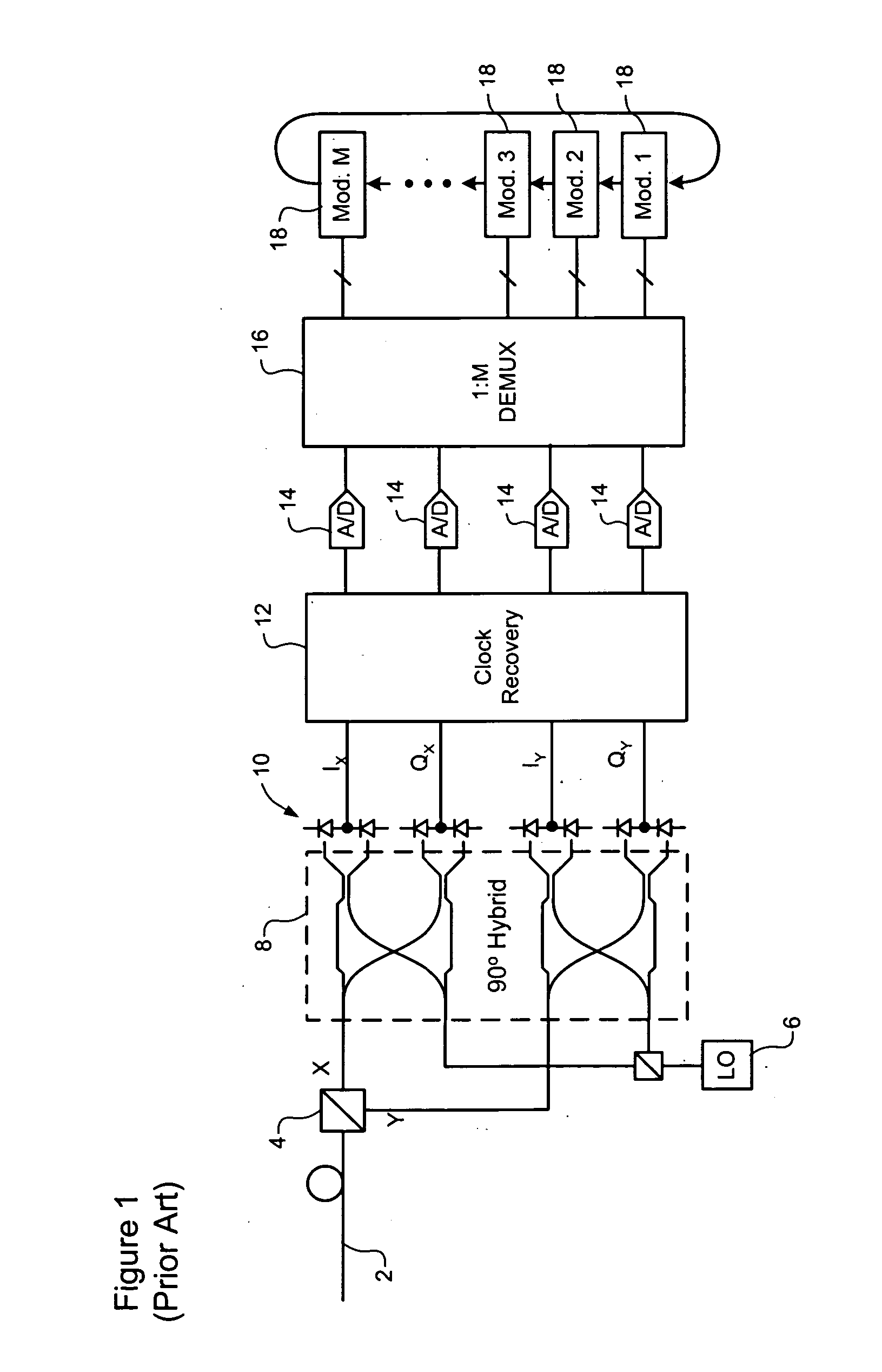
[0027] The present invention provides methods and techniques that enable efficient data transmission in an optical network, with cost-effective signal processing in a receiver unit. Embodiments of the present invention are described below, by way of example only, with reference to FIGS. 2-7b.

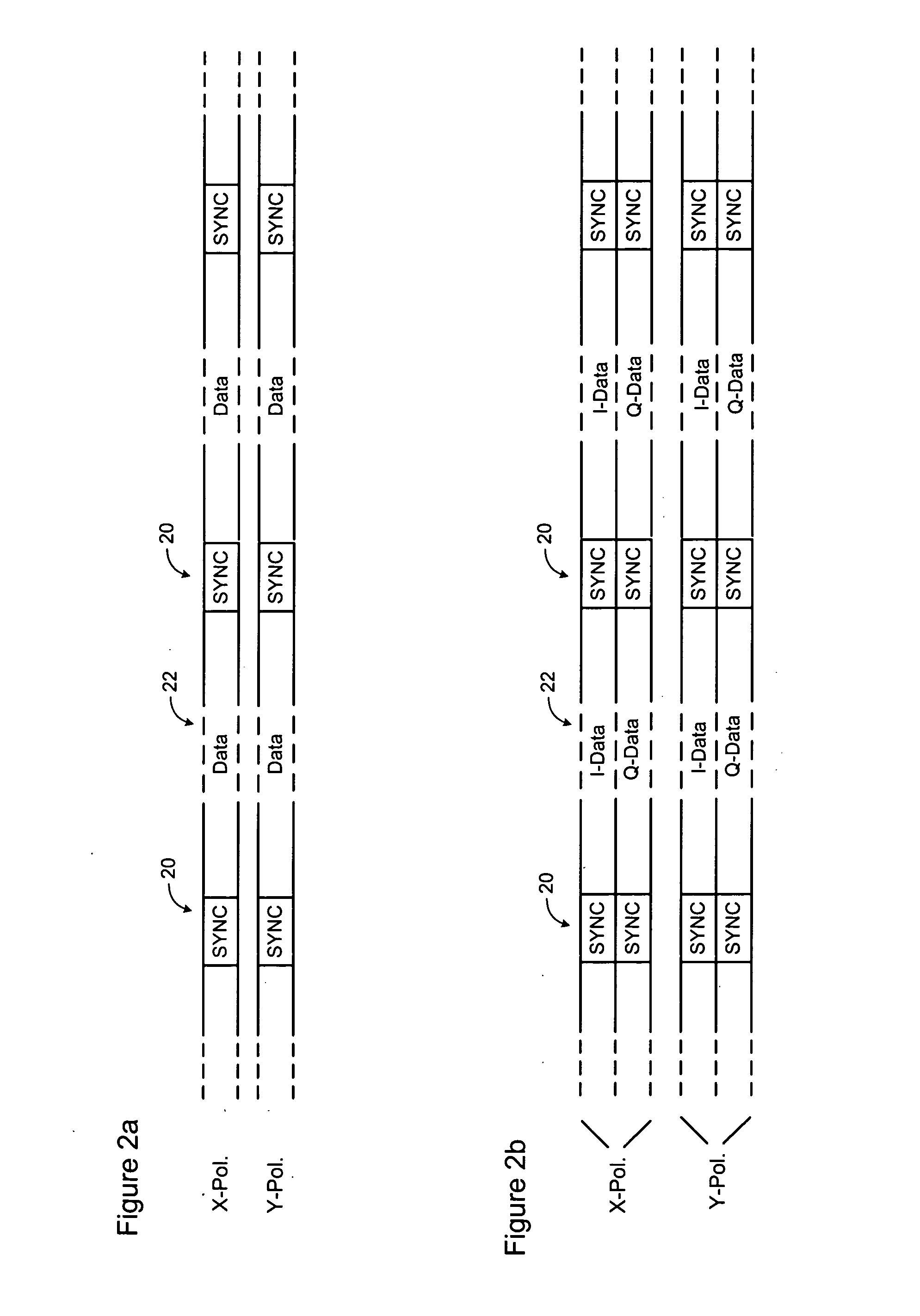
[0028] In general, the present invention provides a system in which periodic SYNC bursts are transmitted through an optical link and used in a receiver to enable efficient receiver training and data recovery. The format, content and repetition rate of the SYNC bursts is selected to facilitate detection even in the presence of significant impairments, while minimizing overhead. For example, in some embodiments, the overhead associated with the SYNC bursts is on the order of 3%. As a result, the performance penalty associated adding the SYNC bursts to the optical signal (and / or the loss of receiver sensitivity resulting from increasing the symbol rate of the optical signal to compensate for the a...


PUM


Abstract

A method of a conveying data through an optical communications system. An optical signal is received through the optical communication system, the optical signal comprising data symbols and SYNC bursts, each SYNC burst having a predetermined symbol sequence. The received optical signal is oversampled to generate a multi-bit sample stream. The sample stream is partitioned into blocks of contiguous samples, wherein each block of samples partially overlaps at least one other block of samples and encompasses at least one SYNC burst and a plurality of data symbols. Each block of samples is independently processed to detect a value of each data symbol.

Description

CROSS-REFERENCE TO RELATED APPLICATIONS [0001] This application claims benefit under 35 U.S.C. 119(e) from U.S. Provisional Patent Application Ser. No. 60 / 728,751, entitled Automatic Gain Control, which was filed on Oct. 21, 2005, under attorney docket No. 13528-250USPR.TECHNICAL FIELD [0002] The present invention relates to optical communications networks, and in particular to methods and systems for efficient data transmission and. training of signal processing functions of a receiver. BACKGROUND OF THE INVENTION [0003] In the optical communications space, techniques used to detect data modulated onto an optical communications signal may be broadly grouped into two classes, namely“direct” detection and “coherent” detection. In “direct” detection techniques, the optical signal is made incident on a photodetector. The electrical current appearing at the photodetector output is proportional to the optical power which is the square of the optical Electric Field (E-Field) magnitude. Da...

Claims


Application Information

Patent Timeline
IPC IPC(8): H04B10/00
CPCH04J3/0608H04J14/06H04L7/027H04L7/048H04L7/0278
Inventor BONTU, CHANDRAWU, KUANG TSANMCNICOL, JOHNROBERTS, KIM B.SUN, HAN
Owner RPX CLEARINGHOUSE
Why Eureka
Try Eureka