
Cartridge and a process for manufacturing a cartridge

a manufacturing process and cartridge technology, applied in the field of cartridges and a process for manufacturing cartridges, can solve the problems of increasing the cost of parts, the surrounding parts of joining parts are prone to deformation, and the coloring material to be incorporated into the transmission resin layer is generally expensive, so as to achieve excellent impact resistance, increase the cost, and avoid the effect of vibration

Inactive Publication Date: 2007-04-26
CANON KK
View PDF53 Cites 33 Cited by
  • Summary
  • Abstract
  • Description
  • Claims
  • Application Information

AI Technical Summary

Benefits of technology

[0018] An object of the present invention is to provide a cartridge and a toner container each of which hardly increases a material cost and is excellent in impact resistance against, for example, a vibration or a fall, the impact resistance being a needed function, as compared to a conventional cartridge. The cartridge and the toner container each cause nearly no deformation of the surroundings of a joining portion and nearly no temperature increase of the surroundings, and are each produced by employing a laser welding method as a joining method imposing a small number of restrictions on joining sites.
[0051] The cartridge of the present invention was obtained on the basis of the finding that the appropriate adjustment of the kind and amount of a material to be incorporated into each of resins of which the first part and the second part are formed can (1) adjust the laser light transmittance of each part to enable the laser welding of each part and (2) secure impact resistance or rigidity as one important product function of a cartridge.
[0053] According to the present invention, there can be provided a cartridge which hardly increases a cost, is excellent in impact resistance, and is hardly susceptible to a vibration, a fall, or the like as compared to a conventional cartridge.

Problems solved by technology

However, a conventional joining technique involves the following problem.
However, in the joining through the injection of a molten resin or the injection of a hot melt, pressure is increased in order that a high-temperature injection material may be injected into each of the joining portions, and, furthermore, an injection material having high viscosity may be injected into each of the joining portions, so the joining involves a problem in that the surroundings of the joining portions are apt to deform owing to heat or pressure.
However, a coloring material to be incorporated into the transmission resin layer is generally expensive, so a cost for a part increases.
In addition, the dye coloring material generally has so poor thermal stability that the material changes its color or generates a gas at the time of molding in some cases.

Method used


Image

  • Cartridge and a process for manufacturing a cartridge
  • Cartridge and a process for manufacturing a cartridge
  • Cartridge and a process for manufacturing a cartridge

Examples


example 1

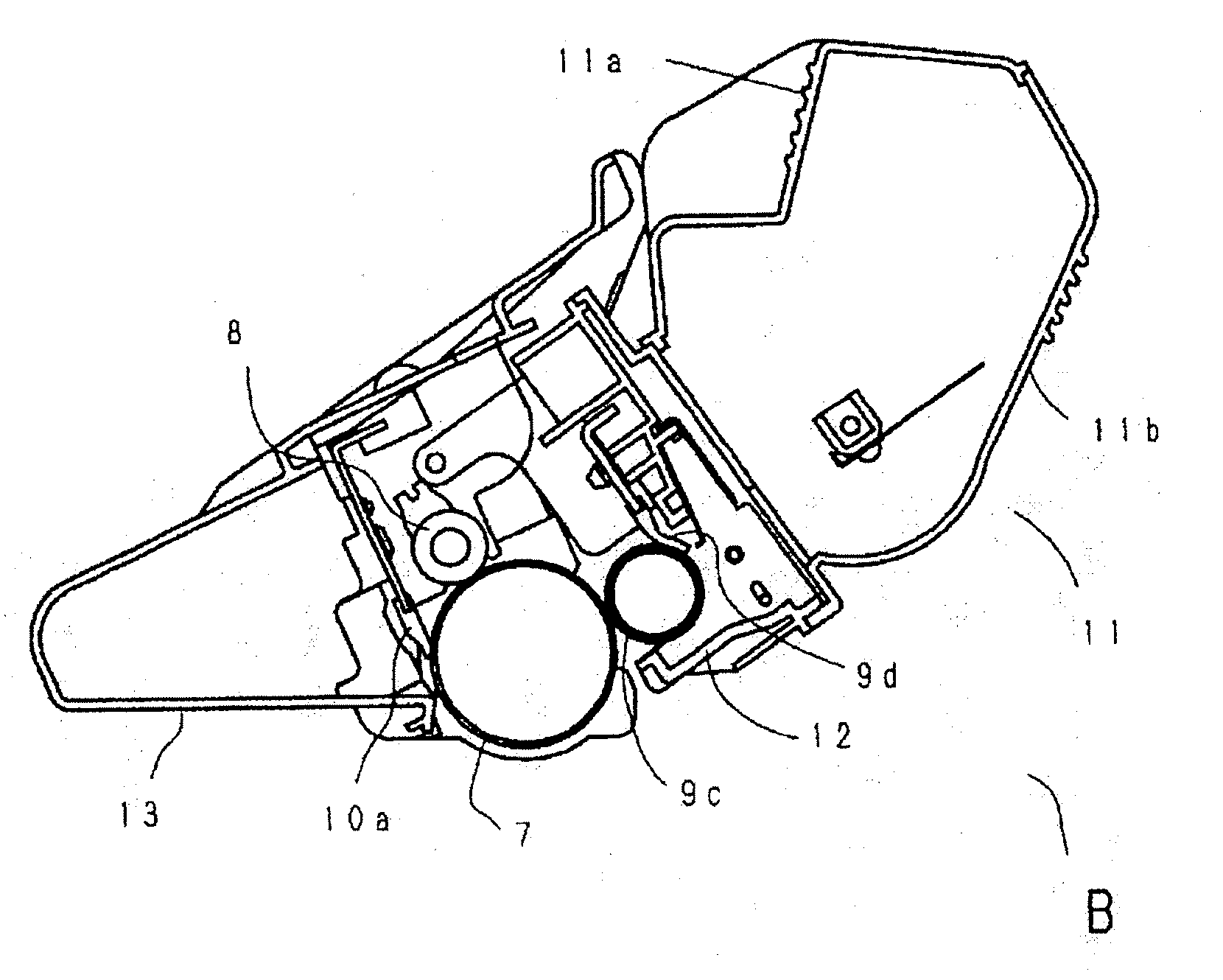
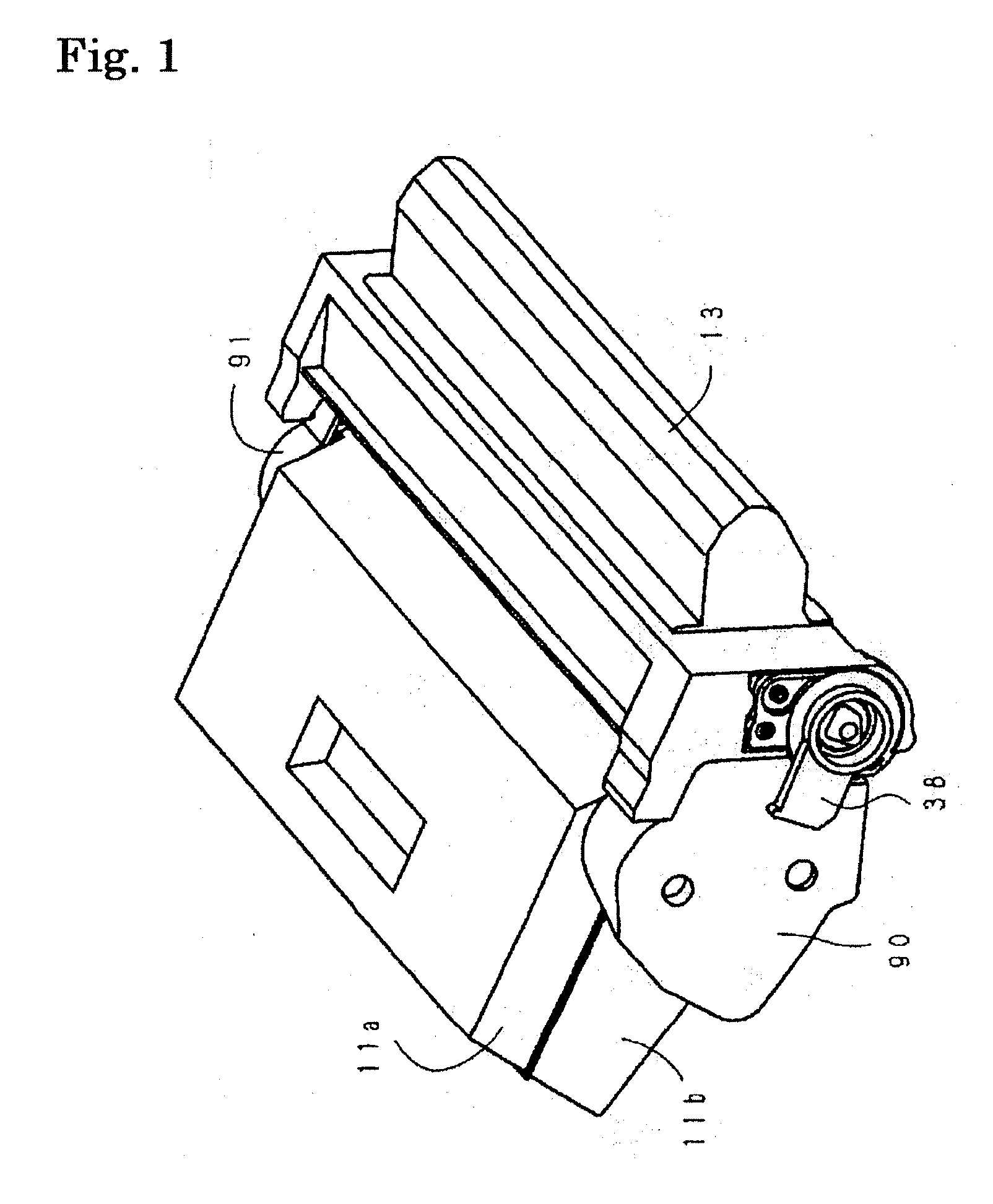
[0144] The drum bearing 38 and the cleaning frame body 13 shown below were joined with each other by a laser welding method on the basis of Embodiment (1). The specifications of a laser welding machine used in the laser welding are as described below.

[0145] Kind of laser light: semiconductor laser, wavelength: 940 nm, output: 30 W, laser spot diameter: 0.6 mm, diameter of laser light with which a joining portion is irradiated: 1.2 mm

[0146] The drum bearing 38 was formed of a laser light transmissive resin composition shown below. The thickness of the drum hearing 38 at a portion to he irradiated with laser light was set to 1.5 mm. The term “laser light transmittance” in the table means the transmittance of semiconductor laser light having a wavelength of 940 nm for a resin plate molded out of the laser light transmissive resin composition and having a thickness of 2 mm.

TABLE 1Laser light transmissive resin compositionPolystyrene (having a weight averageBase material resinmolecul...

example 2

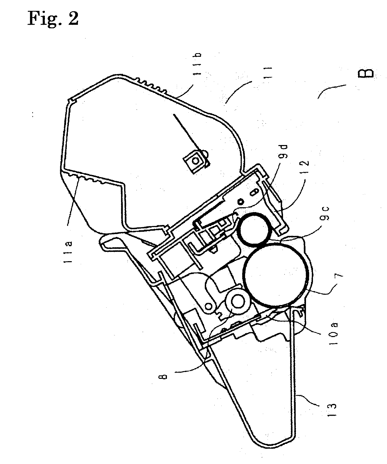
[0148] The toner upper frame body 11a and the toner lower frame body 11b were joined with each other by a laser welding method on the basis of Embodiment (2), whereby a toner container was produced. A laser welding machine having the same specifications as those of Example 1 was used.

[0149] The toner upper frame body 11a was formed of a laser light transmissive resin composition shown below.

TABLE 3Laser light transmissive resin compositionPolystyrene (having a weight averageBase material resinmolecular weight of 9 × 10⁴)Coloring materialNoneRubber-like polymerPolybutadieneContent: 8 parts by mass with respectto 100 parts by mass of polystyreneNumber average particle size: 0.15 μmFlame retardantPhosphate(Aromatic condensed phosphate, tradename: CR 141 manufactured by DAIHACHICHEMICAL INDUSTRY CO., LTD.)Content: 8 parts by mass with respectto 100 parts by mass of polystyreneLaser light80%transmittance(Thickness 2 mm)

[0150] The toner lower frame body 11b was formed of a laser light ...

example 3

[0151] The developing frame body 12 and the toner lower frame body 11b were joined with each other by a laser welding method on the basis of Embodiment (3). A laser welding machine having the same specifications as those of Example 1 was used.

[0152] The developing frame body 12 was formed of a laser light transmissive resin composition shown below.

TABLE 5Laser light transmissive resin compositionPolystyrene (having a weight averageBase material resinmolecular weight of 9 × 10⁴)Coloring materialNoneRubber-like polymerPolybutadieneContent: 8 parts by mass with respectto 100 parts by mass of polystyreneNumber average particle size: 0.15 μmFlame retardantPhosphate(Aromatic condensed phosphate, tradename: CR 741 manufactured by DAIHACHICHEMICAL INDUSTRY CO., LTD.)Content: 8 parts by mass with respectto 100 parts by mass of polystyreneLaser light80%transmittance(Thickness 2 mm)

[0153] The toner lower frame body 11b was formed of the laser light absorptive resin composition of Example 2....


PUM


Abstract

To provide a cartridge and a toner container each of which does not increase a material cost and is excellent in impact resistance against, for example, a vibration or a fall, the impact resistance being a needed function. The cartridge and the toner container each include a first part molded out of a laser light absorptive styrene resin composition and a second part molded out of a laser light transmissive styrene resin composition, the first part and the second part being joined with each other by laser welding. In each of the cartridge and the toner container, the transmittance of each of the parts is adjusted depending on, for example, the particle size and amount of rubber in each of the styrene resin compositions, or the kind of a flame retardant in each of the compositions.

Description

BACKGROUND OF THE INVENTION [0001] 1. Field of the Invention [0002] The present invention relates to a cartridge, which is detachable from an electrophotographic image forming device employing an electrophotographic process such as a laser printer or a copying machine, and a process for manufacturing a cartridge. [0003] The term “electrophotographic image forming device” as used herein refers to a device that employs an electrophotographic image forming process to form an image on a recording medium. Examples of the electrophotographic image forming device include an electrophotographic copying machine, an electrophotographic printer (such as a laser beam printer or an LED printer), a facsimile device, and a word processor. A process cartridge is a member into which charging means, developing means, or cleaning means and an electrophotographic photosensitive member are integrated as a cartridge, the member being detachable from a main body of an image forming device. [0004] 2. Descr...

Claims


Application Information

Patent Timeline
IPC IPC(8): G03G21/18
CPCG03G21/181G03G2221/1876
Inventor SUZUKI, AKIRAANAN, OSAMUMIYAMOTO, JUNHASHIMOTO, KOJI
Owner CANON KK
Learn More