Electronics cooling fan with collapsible fan blade

a cooling fan and collapsible technology, applied in the direction of rotors, vessel construction, marine propulsion, etc., can solve the problems of increasing the difficulty of system design within power and heat dissipation allowances, generating a significant amount of heat for electronic equipment contained within the enclosure, and affecting the operation of the cooling fan

Active Publication Date: 2007-04-26
HEWLETT-PACKARD ENTERPRISE DEV LP
View PDF11 Cites 20 Cited by
  • Summary
  • Abstract
  • Description
  • Claims
  • Application Information

AI Technical Summary

Problems solved by technology

Electronic equipment contained within the enclosure generates a significant amount of heat.
Thermal damage may occur to the electronic equipment unless the heat is removed.
In recent years electronic systems have become more densely packaged so that system design within power and heat dissipation allowances has become more difficult.
This system evolution creates design challenges in aspects of power consumption and the effect of fans on overall system heat dissipation characteristics.
If one or more of the series-connected fans fails due to any of various mechanical or electrical failures, power failure or shutdown due to attempts to operate above a system power budget, physical obstruction of a fan rotor, or the like, the failed fan may create a drag on cooling airflow through the system.
Drag in the airflow pathway can result in increased demand on other fans, overheating of electronic components and devices, and degradation in electronics performance.
Electronics cooling fans typically fail when motor bearing lubricant dries, which may result in a locked rotor.
Fan failure may create heavy resistance to airflow through the electronics system due to blockage created by stationary fan blades.

Method used


Image

  • Electronics cooling fan with collapsible fan blade
  • Electronics cooling fan with collapsible fan blade
  • Electronics cooling fan with collapsible fan blade

Examples


Embodiment Construction

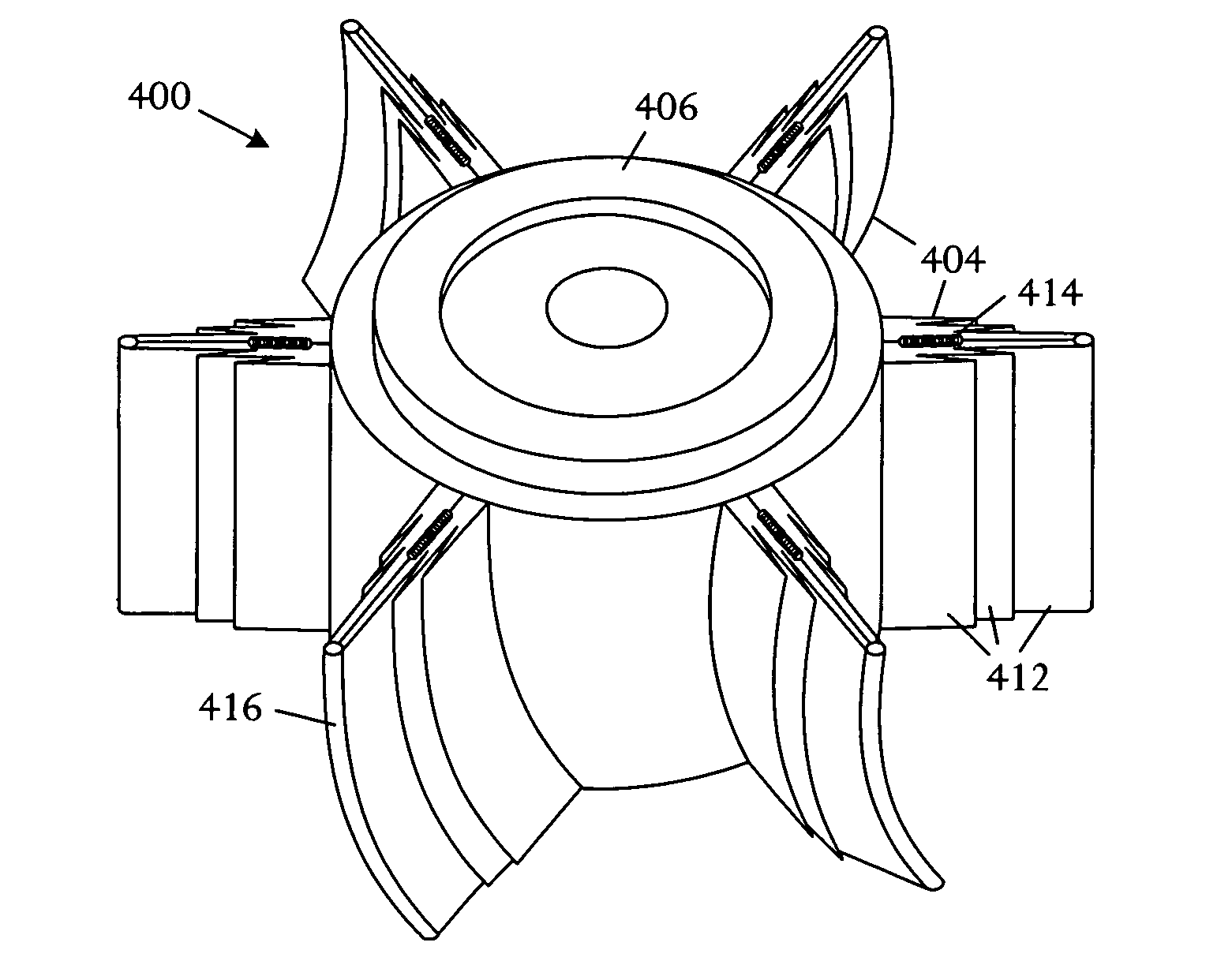
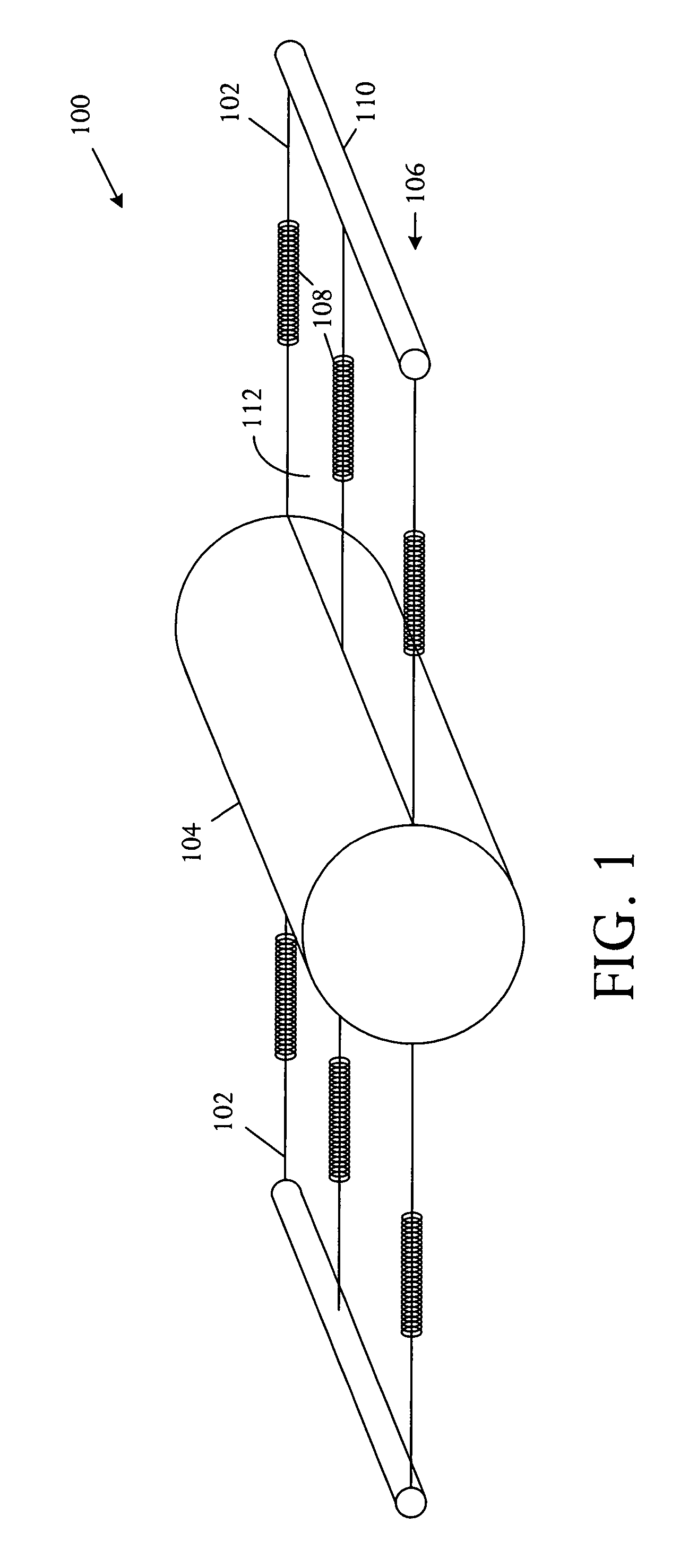
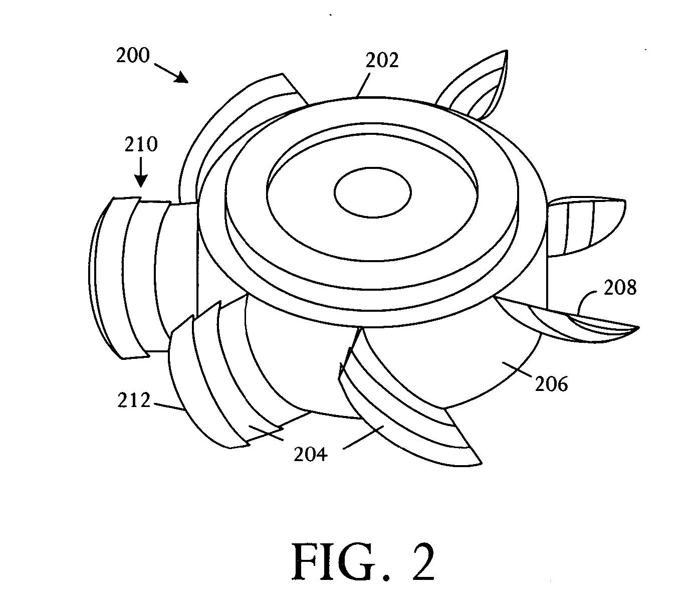
[0013] Referring to FIG. 1, a schematic physical diagram depicts fundamental aspects of various fan rotor systems 100 with collapsible fan blades 102 driven by centrifugal forces. The diagram illustrates a structure and technique enabling reduction of backpressure created by blades of a failed fan. The technique exploits the centrifugal force generated when a fan motor rotates a fan rotor 104. The fan blades 102 are fabricated from a conformal material such as a flexible material, multiple linked collapsible shells, or other arrangements. A spring and mass system 106, comprising springs 108 and masses 110, is attached to a rotor 104 or motor hub and is typically formed underlying an airfoil surface 112. As the motor spins the rotor 104, centrifugal forces overcome the spring force and drive the mass 110 away from the hub 104. The centrifugal forces acting on the masses 110 can fully deploy the flexible airfoil surfaces 112 or collapsible shells, enabling the fan to deliver a pressur...


PUM


Abstract

An electronics cooling fan comprises at least one collapsible fan blade driven by centrifugal force to extend radially as the fan spins and driven by elastic force to retract as spinning slows or stops.

Description

BACKGROUND OF THE INVENTION [0001] Electronic systems and equipment such as computer systems, network interfaces, storage systems, and telecommunications equipment are commonly enclosed within a chassis, cabinet or housing for support, physical security, and efficient usage of space. Electronic equipment contained within the enclosure generates a significant amount of heat. Thermal damage may occur to the electronic equipment unless the heat is removed. [0002] Electronic systems commonly include heat-dissipating components such as processors, central processing units (CPUs), signal processors, and others. One or more fans are used to push air through the system and over components to avoid overheating of the heat-dissipating components. In recent years electronic systems have become more densely packaged so that system design within power and heat dissipation allowances has become more difficult. This system evolution creates design challenges in aspects of power consumption and the...

Claims


Application Information

Patent Timeline
Patent Type & Authority Applications(United States)
IPC IPC(8): B64C27/50
CPCF04D29/382
Inventor MALONE, CHRISTOPHER G.SIMON, GLENN C.ESPINOZA-IBARRA, RICARDO
Owner HEWLETT-PACKARD ENTERPRISE DEV LP
Why Eureka
Try Eureka