Fuel cell system and scavenging method for use in a fuel cell system

a fuel cell and scavenging technology, which is applied in the direction of battery/fuel cell control arrangement, electrochemical generators, transportation and packaging, etc., can solve the disadvantage of loud noise, large amount of water produced by power generation, and small amount of water produced at the anode, so as to reduce noise, reduce energy consumption, and reduce energy consumption

Active Publication Date: 2007-04-26
HONDA MOTOR CO LTD
View PDF0 Cites 58 Cited by
  • Summary
  • Abstract
  • Description
  • Claims
  • Application Information

AI Technical Summary

Benefits of technology

[0014] The present invention has been made taking into consideration the aforementioned problems, wherein an object of the present invention is to provide a fuel cell system, as well as a scavenging method for the fuel ...

Problems solved by technology

If water at any of the electrodes becomes excessive, water clogging may occur.
However, in the fuel cell system, if the power generation period from start to end is short, in some cases, the amount of water produced by power generation is small at the anode, and large only at the cathode.
Further, when the air compressor is operated at a large flow rate, loud noises are produced disadvantageously.
Further, the high capacity air compressor is large and heavy, and consumes a large amount of energy compared to normal capacity air compressors.
Therefore, if operation of the fuel cell system is stopped after operation of the fuel cell system has been started at a temperature below the freezing point, and power generation is performed for a short period of time, or stated otherwise, if operation of the fuel cell system is stopped by action of the driver in a short period of time after operation of the fuel cell has been started at a temperature below the freezing point, it has been found, in some cases, that the fuel cell system ...

Method used


Image

  • Fuel cell system and scavenging method for use in a fuel cell system
  • Fuel cell system and scavenging method for use in a fuel cell system
  • Fuel cell system and scavenging method for use in a fuel cell system

Examples


first embodiment

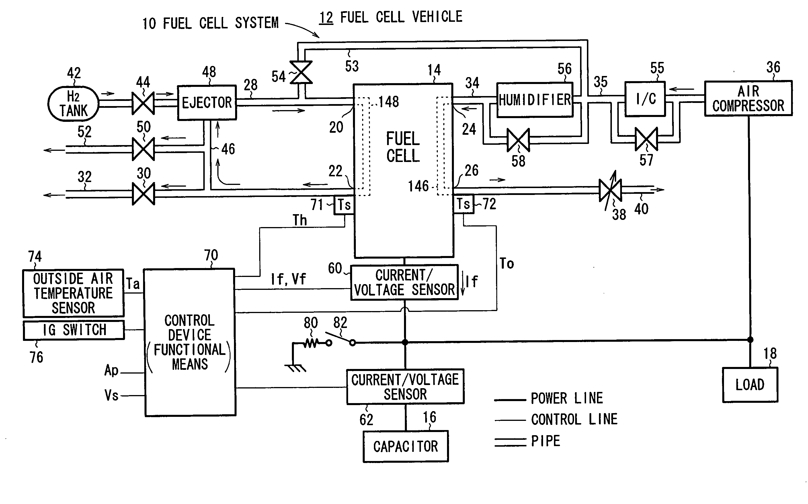
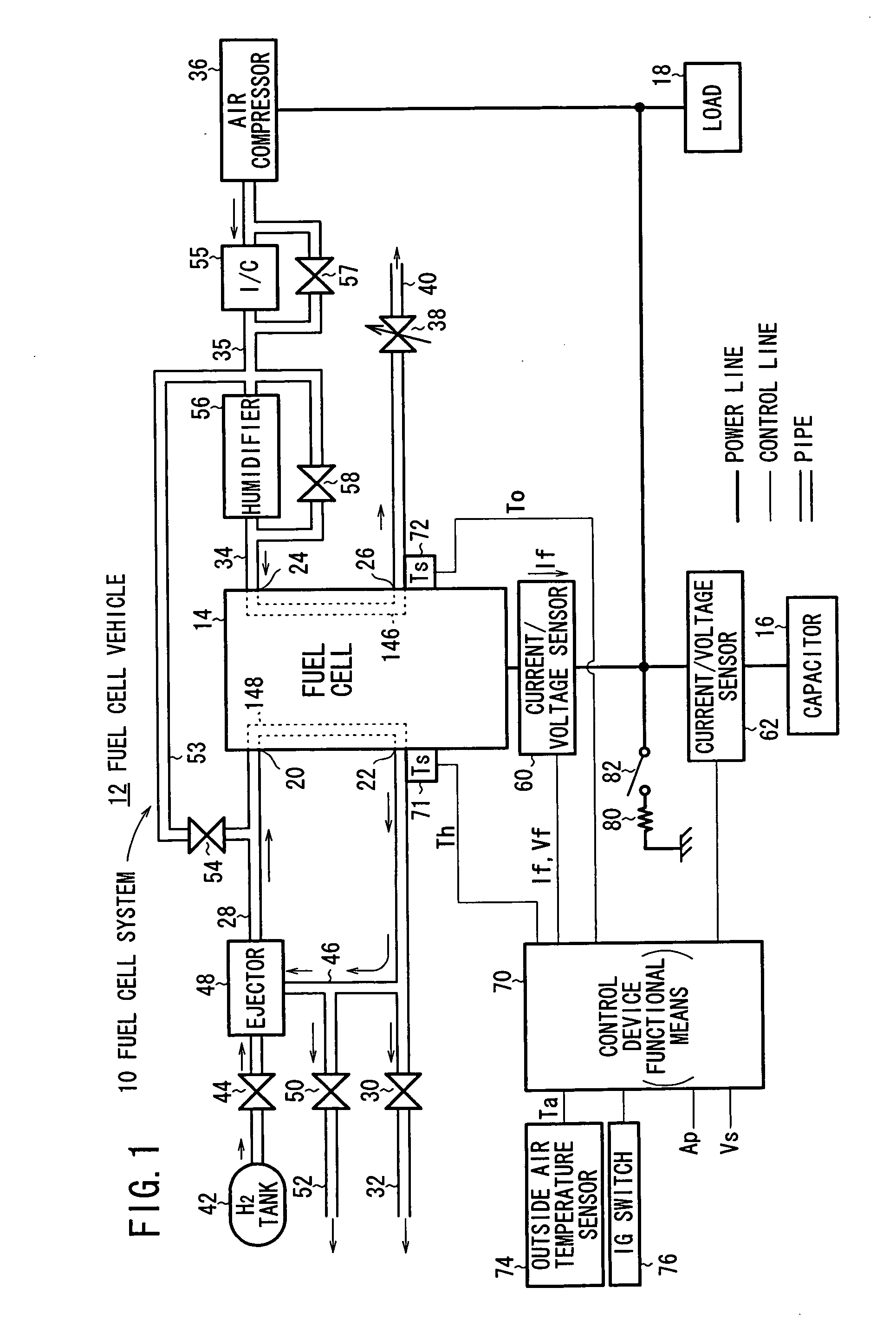
[0086]FIG. 1 is a diagram schematically showing the structure of a fuel cell vehicle 12 equipped with a fuel cell system 10 according to the present invention.

[0087] Basically, the fuel cell vehicle 12 includes a fuel cell 14, a capacitor 16, a load 18 including a motor that is driven to propel the fuel cell vehicle 12, and an auxiliary device such as an air compressor 36. The capacitor 16 serves as an energy storage means, in which a power generation current If of the fuel cell 14 is stored, and which assists the output of the fuel cell 14. For example, an electric double layer capacitor may be used as the capacitor 16. A battery may be used as an energy storage means instead of the capacitor 16, or both a battery and a capacitor 16 may be used.

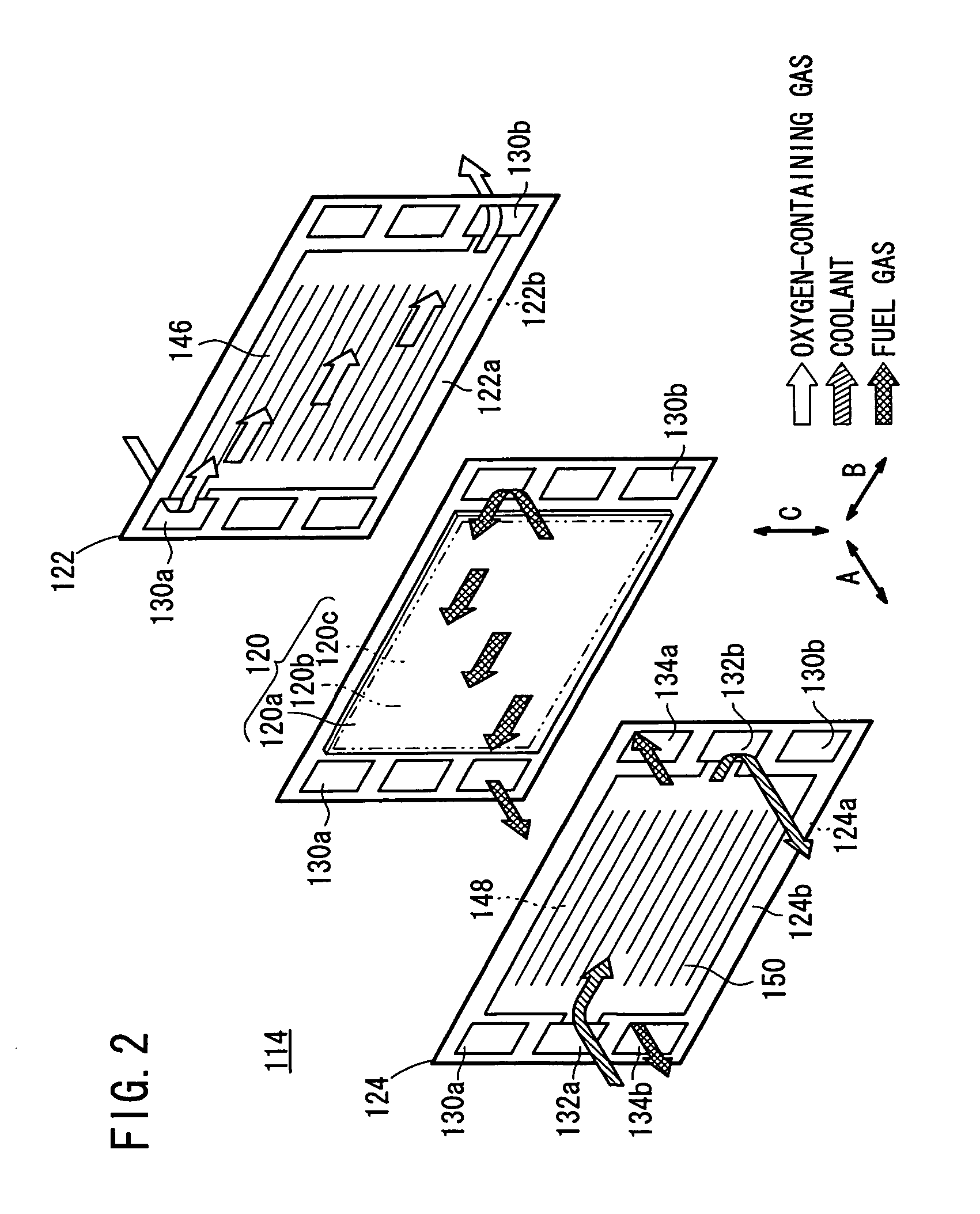
[0088] The fuel cell 14 has a stacked structure, which is formed by stacking a plurality of cells each including an anode, a cathode, and a solid polymer electrolyte membrane interposed between the anode and the cathode.

[0089] Specifically...

second embodiment

[0168]FIG. 12 is a diagram schematically showing the structure of a fuel cell vehicle 12A equipped with a fuel cell system 10A according to the present invention.

[0169] The fuel cell system 10A differs from the fuel cell system 10 shown in FIG. 1, in that the fuel cell system 10A further includes a flow rate sensor (flow rate detection means) 89 disposed in the hydrogen supply channel 28, for measuring a volume flow rate in order to determine the hydrogen consumption amount. Further, a flow rate sensor or a flow rate meter (flow rate detection means) 91 also is disposed in the air discharge channel 40, for measuring a volume flow rate in order to determine an accumulated air flow amount. In addition, a humidification sensor (humidification detection means) 92 for measuring a relative humidity RH in the air discharge channel 40, and a wind speed sensor (wind speed detection means) 93 for measuring wind speed, are provided. The flow rate sensors 89, 91, and the humidification sensor 9...

third embodiment

[0191]FIG. 15 is a diagram schematically showing the structure of a fuel cell vehicle 12B equipped with a fuel cell system 10B, according to the present invention.

[0192] The fuel cell system 10B differs from the fuel cell system 10 shown in the example of FIG. 1, in that the fuel cell system 10B additionally includes a flow rate sensor (flow rate detection means) 91 provided in the air discharge channel 40, for measuring a volume flow rate and to determine an accumulated air flow rate, and a humidification sensor (humidification detection means) 92, for measuring a relative humidity RH in the air discharge channel 40. Further, in FIG. 15, a dilution box 90, which is connected to the hydrogen purge channel 32 and the discharge channel 52, a further discharge channel 94 having one end connected to the discharge port of the dilution box 90 and the other end connected to the outside, and a timer 73 provided in the control device 70, also are shown. As described above, the dilution box 9...


PUM


Abstract

After an ignition switch is turned off, in order to suppress operation of an air compressor and thereby reduce noise, liquid droplets residing in an oxygen-containing gas flow field as well as liquid droplets residing in a fuel gas flow field are removed during separate time periods, such that the flow rate in the oxygen-containing gas flow field and the flow rate in the fuel gas flow field do not become large at the same time. Then, an electrolyte membrane is dried using an oxygen-containing gas, in order to improve the performance upon starting a next operation.

Description

BACKGROUND OF THE INVENTION [0001] 1. Field of the Invention: [0002] The present invention relates to a fuel cell system and a scavenging method for use in a fuel cell system, in which scavenging of at least one of a fuel gas flow field and an oxygen-containing gas flow field can be performed at the time of stopping power generation, or after stopping power generation, in order to prepare for the initiation of a next operation of the fuel cell system, which operates at a low temperature, such as a temperature below the freezing point. [0003] 2. Description of the Related Art: [0004] By way of example, a polymer electrolyte fuel cell employs a membrane electrode assembly, which includes an anode (fuel electrode) and a cathode (air electrode), and a polymer electrolyte membrane interposed between the electrodes. The electrolyte membrane is an ion exchange membrane. The membrane electrode assembly is sandwiched between a pair of separators. A fuel gas flow field is formed between the a...

Claims


Application Information

Patent Timeline
IPC IPC(8): H01M8/04
CPCH01M8/04007H01M8/04126H01M8/04179H01M8/04223H01M2008/1095Y02E60/50B60L58/30H01M8/0267H01M8/241H01M8/04225H01M8/04228H01M8/04302H01M8/04303H01M8/2457H01M8/2483Y02T90/40H01M8/0258
Inventor WAKE, CHIHIROINAI, SHIGERUMIYATA, KOICHIRO
Owner HONDA MOTOR CO LTD
Why Eureka
Try Eureka