Methods for fabricating multi-terminal phase change devices

a phase change device and multi-terminal technology, applied in semiconductor/solid-state device manufacturing, basic electric elements, electric devices, etc., can solve the problems of device electrical characteristics that affect the electrical characteristics of the device, device electrical characteristics that are disputed, etc., to achieve the effect of not increasing the resistance across the two conducting elements of the switch, increasing the resistance of the heater element, and manifolds

Inactive Publication Date: 2007-05-03
AGATE LOGIC BEIJING
View PDF19 Cites 88 Cited by
  • Summary
  • Abstract
  • Description
  • Claims
  • Application Information

AI Technical Summary

Benefits of technology

[0011] In accordance with one aspect of the invention, a multi-terminal phase change device (PCD) is provided, allowing separation of the Set / Reset controls from the target electrical path. One way of accomplishing this is by constructing a device that consists of a phase change material (PCM) that connects to a conducting terminal(s) in an electrical path. Other terminal(s) used to control the Set / Reset operations through heater element(s) are connected separately to the PCM. This structure allows an application in which an electrical connection can be created between two terminals, with the control of the connection being effected using a separate terminal or terminals. The benefits are manifold. The resistance of the heater element can be increased independently from the resistance of the path between the two conductive terminals. This allows the use of smaller heater elements thus requiring less current to create the same amount of Joule heating per unit area. The resistance of the heating element does not impact the total resistance of the PCD. As the improvements are done to the heater element the resistance across the two conducting elements of the switch is not increased. The programming control can be placed outside of the main signal path through the PCD, reducing the impact of the associated capacitance and resistance of the device.

Problems solved by technology

A problem associated with the two-terminal device structure depicted in FIG. 1 is that the heating element must be incorporated at one end of the device, which means that the heating element is directly in the electrical path between the two terminals of the device which directly affects the electrical characteristics of the device.
This causes contention between the electrical characteristics of the device during its programming state and its read or non-programming state.
Another issue with two-terminal devices is that the circuitry needed to program the device is directly connected to one or both of the terminals of the device.

Method used


Image

  • Methods for fabricating multi-terminal phase change devices
  • Methods for fabricating multi-terminal phase change devices
  • Methods for fabricating multi-terminal phase change devices

Examples


Embodiment Construction

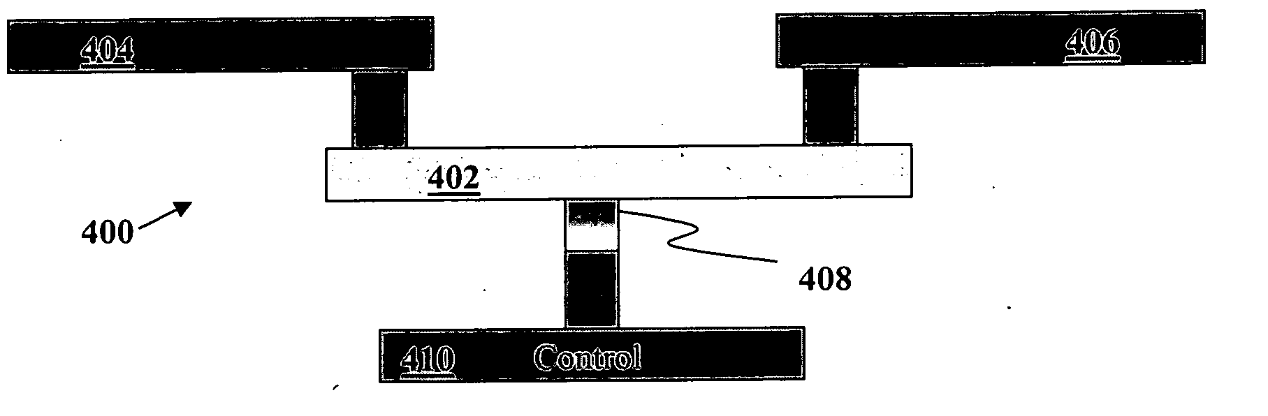
[0043]FIG. 4A shows an example of a three-terminal PCD (phase change device) 400 in accordance with the invention. PCD 400 includes a pair of active electrically conductive terminals, 404, 406, bridged together by phase change material (PCM) 402. Terminals 404 and 406 connect PCD 400 to other circuit devices (not shown) whose exact nature depends on the particular application.

[0044] PCM 402 is in thermal and electrical contact with a heating element 408, which is part of a control terminal 410 through which current is applied to the heating element to activate same. When activated in a controlled manner as explained further below, heating element 408 induces a phase change in PCM 402. Two important phases are a high resistance amorphous phase, which causes the PCM 402 to be effectively high resistance, thereby establishing a virtual open circuit condition between active terminals 404 and 406, and a low resistance polycrystalline phase, which electrically connects the active termina...


PUM


Abstract

Phase change devices, and particularly multi-terminal phase change devices, include first and second active terminals bridged together by a phase-change material whose conductivity can be modified in accordance with a control signal applied to a control electrode. This structure allows an application in which an electrical connection can be created between the two active terminals, with the control of the connection being effected using a separate terminal or terminals. Accordingly, the resistance of the heater element can be increased independently from the resistance of the path between the two active terminals. This allows the use of smaller heater elements thus requiring less current to create the same amount of Joule heating per unit area. The resistance of the heating element does not impact the total resistance of the phase change device. The programming control can be placed outside of the main signal path through the phase change device, reducing the impact of the associated capacitance and resistance of the device.

Description

BACKGROUND OF THE INVENTION [0001] 1. Field of the Invention [0002] The invention relates to phase change devices (PCDs) used in logic and memory applications. [0003] 2. Description of the Related Art [0004] A two-terminal phase change device (PCD) 10 is shown in FIG. 1, and consists of a heating element 14 connected to a control terminal B. Heating element 14 acts as both a heater and an electrically conducting node in thermal and electrical contact with phase change material (PCM) 12, which connects to another metal terminal A which is simply an electrically conducting node connecting the PCD 10 to other circuitry (not shown). An electrical schematic of PCD 10 is shown in the right-hand side of FIG. 1, with the heating element 14 being represented as a resistance Rheater, and the PCM 12 being represented as a resistance RPCM. [0005] In operation, a programming pulse is applied to PCD 10 in such a way as to selectively create a high resistance state or a low resistance state in the...

Claims


Application Information

Patent Timeline
Patent Type & Authority Applications(United States)
IPC IPC(8): H01L21/3205H01L21/4763
CPCH01L45/06H01L45/1206H01L45/122H01L45/1226H01L45/126H01L45/1683H10N70/253H10N70/821H10N70/823H10N70/231H10N70/8413H10N70/066
Inventor OLIVA, ANTONIETTAKORDUS, LOUIS CHARLES IIDERHACOBIAN, NARBEHCHAN, VEI-HANSTEWART, THOMAS E. JR.
Owner AGATE LOGIC BEIJING
Why Eureka
Try Eureka