Multi-tier benefit optimization for operating the power systems including renewable and traditional generation, energy storage, and controllable loads

a technology of power system and benefit optimization, applied in the direction of machines/engines, process and machine control, instruments, etc., can solve the problems of periodic swings in availability of underlying energy sources, escalating fuel extraction costs, and recurring shortages of fuels, etc., to achieve maximum benefit

Active Publication Date: 2007-05-03
GENERAL ELECTRIC CO
View PDF4 Cites 146 Cited by
  • Summary
  • Abstract
  • Description
  • Claims
  • Application Information

AI Technical Summary

Benefits of technology

[0004] The disclosure delineates an intelligent renewable based system. The system has a controller with memory and a program stored in the memory. A plurality of data structures forms the program. The program data structures control a multi-tier optimization of a power grid. The power grid has connected thereto water and power generating assets and controllable loads. The multi-tier benefit optimization program maximizes the benefit generated by the renewable power generating assets, water generating assets and the controllable loads.

Problems solved by technology

However, these energy sources all have significant disadvantages including pollution, periodic shortages and escalating costs of extracting the fuels.
However, this is not to say these technologies are without difficulties.
One difficulty with these technologies is that the underlying energy sources i.e., wind, sunlight and water can be subject to periodic swings in availability, e.g., the sun may eclipse, the winds may subside, and water levels may fall due to extended periods of drought.
Another difficulty is that the best locations for capturing the foregoing energy sources are often remote from where the energy is used.
Most of the remote locations near large bodies of water are already in use i.e., future growth of hydropower installations is limited.
This may not be the most efficient use of the generated energy from an economic standpoint.
As is well known, connecting a wind or hydro powered turbine generator to a utility grid imposes certain constraints on the generator.
When this occurs, the energy that could be captured is simply wasted.
Such systems are relatively expensive to install and result in efficiency losses of their own due to the repeated energy conversions.

Method used


Image

  • Multi-tier benefit optimization for operating the power systems including renewable and traditional generation, energy storage, and controllable loads
  • Multi-tier benefit optimization for operating the power systems including renewable and traditional generation, energy storage, and controllable loads
  • Multi-tier benefit optimization for operating the power systems including renewable and traditional generation, energy storage, and controllable loads

Examples


Embodiment Construction

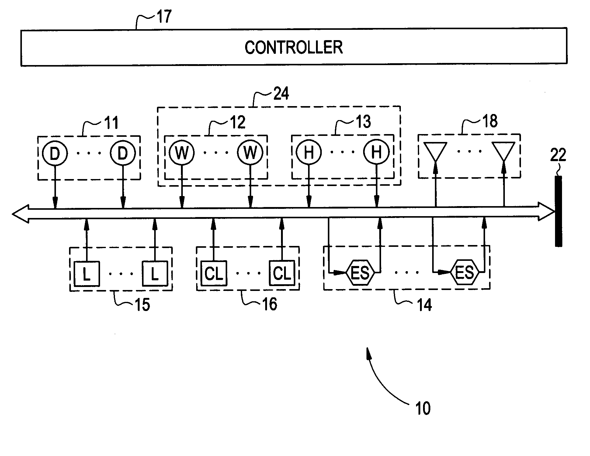
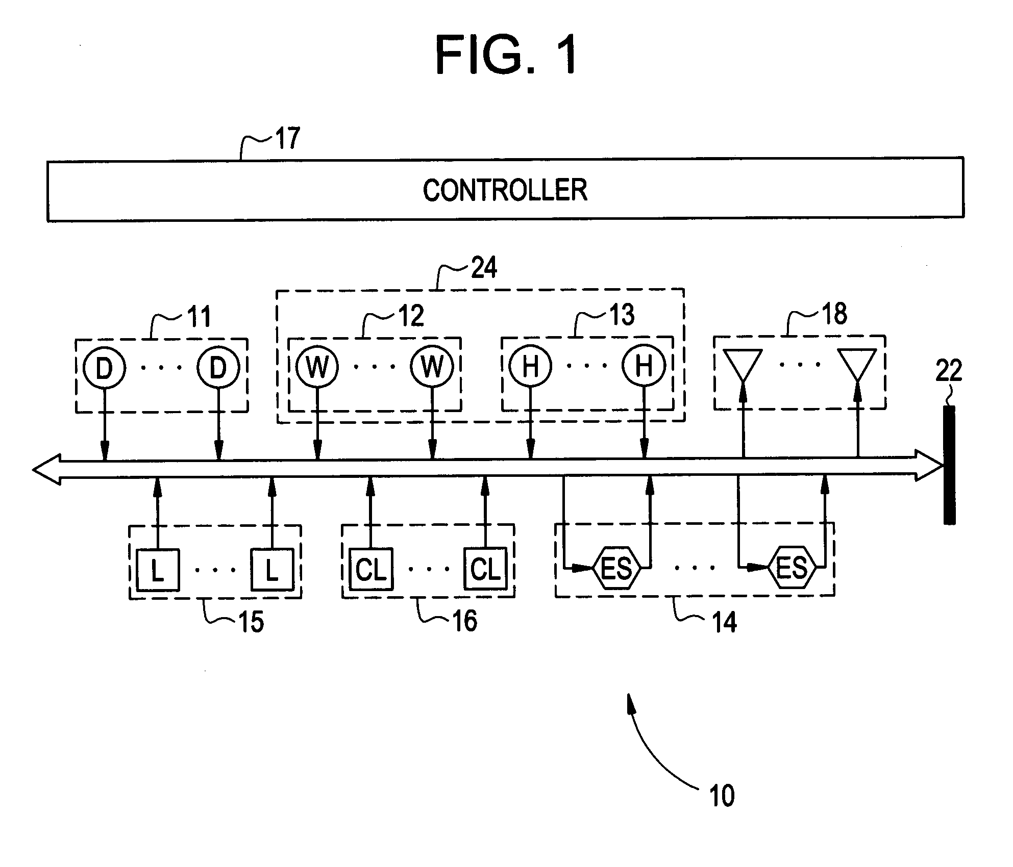
[0012] The disclosure delineates a locally controllable power grid 10, FIG. 1 that may, if desired, be connected to a utility power grid 22. Examples of locally controlled power grids are an island power grid that is not connected to one of the utility power grids or an electric ship microgrid like the power grid aboard an aircraft carrier. The local power grid 10 may, if desired, have connected thereto a fossil fueled generating asset 11 and renewable power generating assets 24. An example of a fossil fueled generating asset 11 is a diesel engine that has drive electricity producing generators. Examples of a renewable power-generating asset 24 include wind powered generating assets 12, water powered assets, water generating assets, water storage assets, hydroelectric powered generating assets 13, solar, geothermal, and hydrogen engine-generators in concert with an electorlyser plant and hydrogen storage units. If desired, energy storage units 14 capable of regenerating electric pow...


PUM


Abstract

A plurality of power generating assets are connected to a power grid. The grid may, if desired, be a local grid or a utility grid. The power grid is connected to a plurality of loads. The loads may, if desired, be controllable and non-controllable. Distribution of the power to the loads is via a controller that has a program stored therein that optimizes the controllable loads and the power generating assets. The optimization process is via multi-tier benefit construct.

Description

BACKGROUND OF THE INVENTION [0001] Most energy produced today is derived from fossil fuels such as oil, coal and natural gas. However, these energy sources all have significant disadvantages including pollution, periodic shortages and escalating costs of extracting the fuels. [0002] By contrast, solar, wind and hydroelectric energy systems all offer the advantages of being relatively safe and reliable. Moreover, these technologies have the common advantage of drawing their power from sources that are virtually inexhaustible. However, this is not to say these technologies are without difficulties. One difficulty with these technologies is that the underlying energy sources i.e., wind, sunlight and water can be subject to periodic swings in availability, e.g., the sun may eclipse, the winds may subside, and water levels may fall due to extended periods of drought. Another difficulty is that the best locations for capturing the foregoing energy sources are often remote from where the e...

Claims


Application Information

Patent Timeline
Patent Type & Authority Applications(United States)
IPC IPC(8): F03D9/00H02J3/38
CPCH02J3/383H02J3/386Y02E10/563Y02E10/763H02J3/382H02J2300/40H02J2300/28H02J2300/20H02J2300/24H02J3/381Y02E10/56Y02E10/76H02J3/48H02J3/50
Inventor BALAN, CHELLAPPABOSE, SUMITYE, ZHIHONGBEBIC, JOVANDE BEDOUT, JUANLIU, YANGARCES, LUIS
Owner GENERAL ELECTRIC CO
Why Eureka
Try Eureka