
Engine and a method of making same

a manufacturing method and internal combustion engine technology, applied in the direction of manufacturing tools, machines/engines, crankcase compression engine lubrication, etc., can solve the problems of cylinder wall scuffing and piston friction remaining a major contributor to fuel consumption in internal combustion engines, and achieve reasonable piston friction characteristics, reduce cylinder-piston friction and wear characteristics, good oil retention

Inactive Publication Date: 2007-05-10
FORD GLOBAL TECH LLC
View PDF8 Cites 33 Cited by
  • Summary
  • Abstract
  • Description
  • Claims
  • Application Information

AI Technical Summary

Benefits of technology

[0005] While conventional cross hatch honing creates cylinder walls having good oil retention and giving reasonable piston friction characteristics, piston friction remains a major contributor to fuel consumption in internal combustion engines. It is therefore desirable to further reduce the cylinder-piston friction and wear characteristics.
[0006] The inventor herein has realized that it is possible to obtain reduced piston friction and wear characteristics without penalizing oil consumption by use of elongate pockets having axes which are substantially parallel to the axis of the cylinder bore to the regions supporting the piston when at top dead center and bottom dead center.
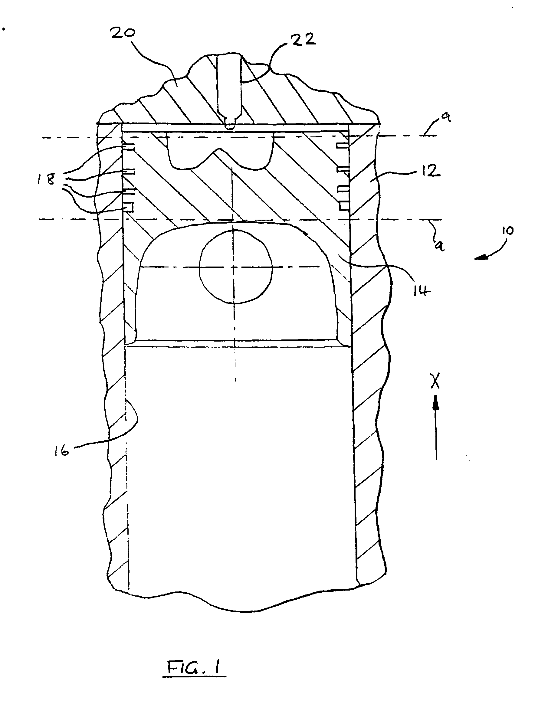
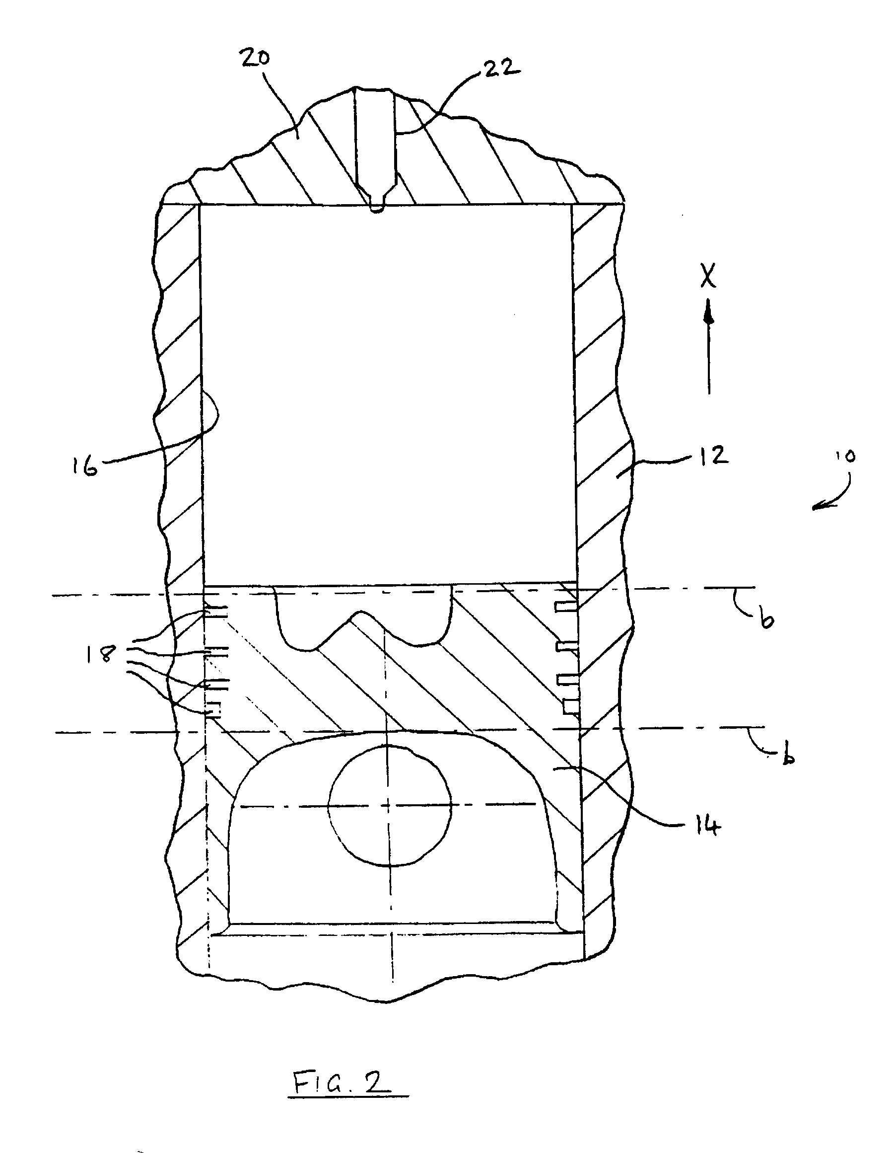
[0007] Accordingly, there is provided an internal combustion engine having at least one cylinder bore said cylinder bore having a wall for slidingly supporting a piston, said wall having pockets formed therein for retaining lubricant to reduce friction between the cylinder bore and piston, wherein said pockets are elongate and have axes which are substantially parallel to axis of said cylinder bore, said pockets being located at a first region of said wall supporting the piston when said piston is at its top dead center position.
[0014] According to another embodiment of the present invention, there is provided a method for manufacturing a cylinder for an internal combustion engine, the method including: producing a cylinder bore wall with a required diameter and roundness; and machining pockets in said cylinder bore wall, which pockets, in use, retain lubricant to reduce friction between said cylinder bore and a piston slidingly supported by said cylinder bore, characterised in that said pockets are elongate and formed with axes which are substantially parallel to the axis of said cylinder bore, said pockets being machined at a first region which, in use, supports said piston when said piston is at its top dead center position.

Problems solved by technology

A problem encountered with cylinder walls having grooves created in this manner is that, in use, continuous grooves encourage blow-by of exhaust gases past the piston rings.
A further problem is that cylinder wall scuffing tends to occur when there is no discontinuity in the cylinder wall surface in the direction of travel of the piston.
While conventional cross hatch honing creates cylinder walls having good oil retention and giving reasonable piston friction characteristics, piston friction remains a major contributor to fuel consumption in internal combustion engines.

Method used


Image

  • Engine and a method of making same
  • Engine and a method of making same
  • Engine and a method of making same

Examples


Embodiment Construction

)

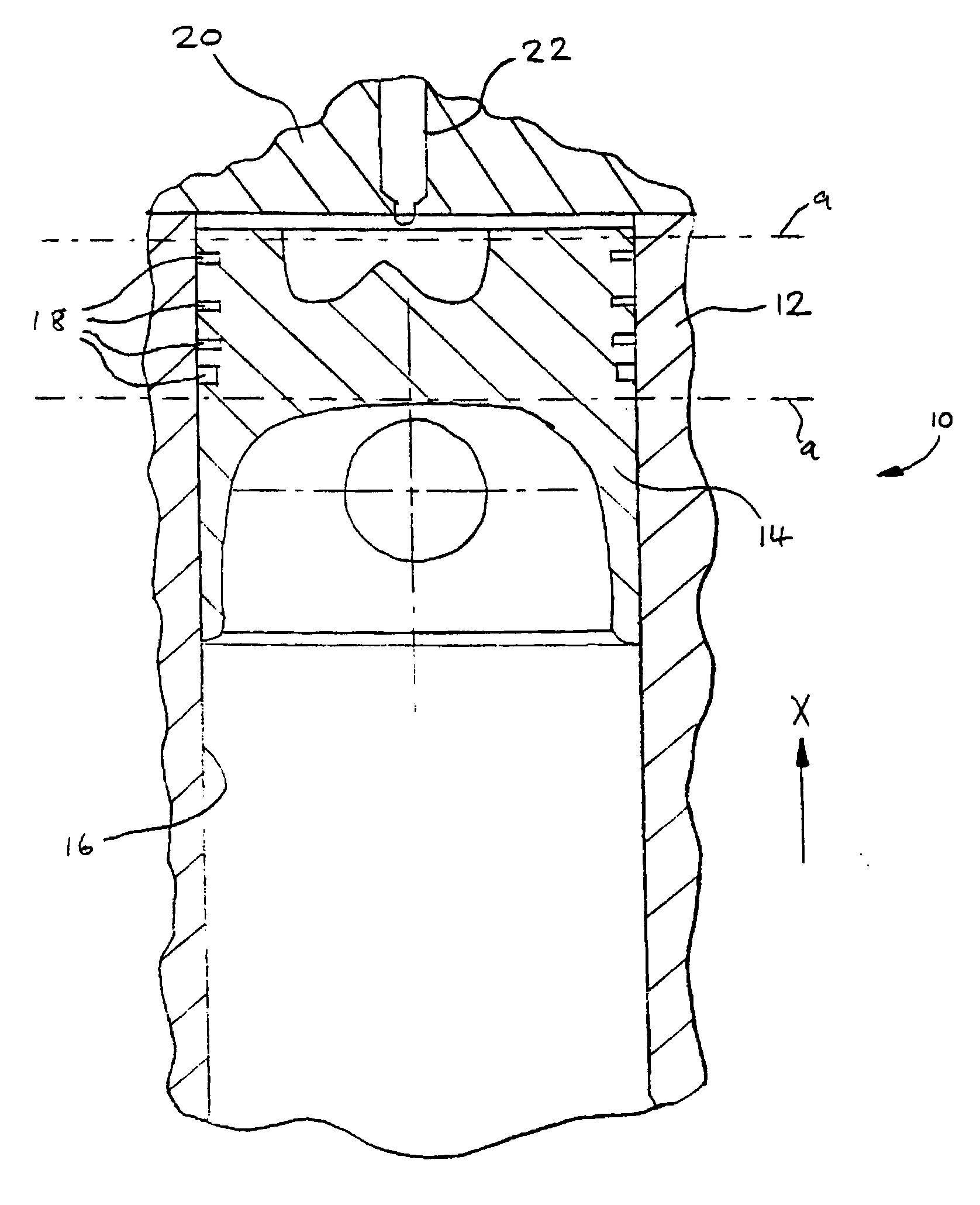
[0027] With reference to FIGS. 1 and 2 there is shown a section through one cylinder 10 of a multi-cylinder diesel internal combustion engine. The cylinder 10 is formed within a cylinder block 12 of the engine, and a piston 14 is slidingly supported by the cylinder bore wall 16 and has a number of piston rings 18 to provide a seal between the piston 14 and the cylinder bore wall 16. FIG. 1 shows the cylinder 10 with the piston 14 occupying its top dead center position, while FIG. 2 shows the cylinder 10 with the piston 14 occupying its bottom dead center position.

[0028] A cylinder head 20 is attached to the cylinder block 12 by way of fasteners (not shown) to close of the upper end of the cylinder 10 and supports a number of valves (not shown) to selectively admit air into the cylinder 10 and to selectively allow exhaust gases to flow out of the cylinder 10. A fuel injector nozzle 22 is supported by the cylinder head 20 for injecting fuel into the cylinder 10.

[0029] As depicted i...


PUM

PropertyMeasurementUnit
Lengthaaaaaaaaaa
Lengthaaaaaaaaaa
Lengthaaaaaaaaaa

Abstract

An internal combustion engine is provided having at least one cylinder bore for slidingly supporting a piston, the cylinder bore wall of the at least one cylinder of the engine having pockets formed therein for retaining lubricant to reduce friction between the cylinder bore wall and piston. The pockets are elongate and have axes which are substantially parallel to the axis of the cylinder bore. The pockets are located at a first region supporting the piston when the piston is at its top dead center position. A method of making the cylinder is also provided.

Description

FIELD OF THE INVENTION [0001] This invention relates to an internal combustion engine and in particular to method and a system for manufacturing an internal combustion engine. BACKGROUND AND SUMMARY OF THE INVENTION [0002] It is known that it is necessary to have a certain degree of roughness on each cylinder wall of an engine in order to retain oil used as a lubricant between the cylinder wall and the piston which is slidingly engaged within the respective cylinder. In practice the surface of the cylinder wall comprises a number of peaks and troughs and the oil is stored within the troughs. It is further well known in the manufacture of internal combustion engines to use a honing process to produce a desired surface finish on the wall of each cylinder of the engine in order to provide such an oil retention surface. [0003] DE19614328 describes a process for the fine machining of work piece surfaces by means of laser beams to generate a regular surface finish. Various examples are gi...

Claims


Application Information

Patent Timeline
IPC IPC(8): F01M3/04F02F3/00B23K26/00B23K26/38F02F1/20F16J10/04
CPCB23K26/0078B23K26/385B23K2201/003B23K2201/006F02F1/20F16J10/04B23K26/389B23K26/3584B23K2101/003B23K2101/006B23K26/36F02F1/004
Inventor PEGG, IAN
Owner FORD GLOBAL TECH LLC
Learn More