
Three-dimensional color image recording apparatus

Inactive Publication Date: 2007-05-10
PANASONIC CORP
View PDF6 Cites 14 Cited by
  • Summary
  • Abstract
  • Description
  • Claims
  • Application Information

AI Technical Summary

Benefits of technology

[0007] The invention, relating to an apparatus which records a three-dimensional color image by means of a holography, enables a provision of an apparatus with a simple system configuration which can shift a phase of a reference beam accurately and quickly, and can also simultaneously record a color phase shift hologram.
[0008] As an improvement, the invention displays a lattice fringe on a spatial light modulator such as a liquid crystal panel or a digital mirror device panel, irradiates it with laser beams in three primary colors red, green and blue, and uses a primary diffracted beam created by the lattice fringe as an image recording reference beam. On moving the same lattice fringe on the modulator, a phase of the diffracted beam shifts due to a movement of a fringe, a phase shift amount of the beam is proportionate to only an amount of movement of the fringe, and becomes unconnected to a wavelength of the beam. For example, in a case in which a light and dark of the lattice fringe displayed on the modulator is inverted and the fringe moved by a half of a lattice interstice, the phase of the primary diffracted beam shifts by precisely π. By this method, as an optical phase can be accurately shifted rendering unnecessary a device for detecting or regulating the optical phase, a system configuration of an image recording apparatus becomes simple. Also, as the phase shift amount does not depend on the beam wavelength, a simultaneous recording of a color phase shift hologram in a three-dimensional image is possible.
[0009] As the apparatus in the invention, being able to carry out a switching of the displayed lattice fringe at a high speed by means of an electronic operation, can simultaneously record RGB images, it is possible to record a high-quality three-dimensional color image at a high speed. Furthermore, as the system configuration can be made simple, it is possible to develop a compact and low-priced three-dimensional color image recording apparatus.

Problems solved by technology

With the method inserting the glass plate, although a system configuration of a recording apparatus is simple, as it is difficult to insert and remove the glass plate at a high speed, the method is not suitable for a high-speed recording.
With the method using the piezoelectric element, as a control device which detects the optical phase and regulates the position of the mirror is necessary, the apparatus which carries out the optical phase shift is extensive and expensive.
Also, with heretofore known methods, as a phase shift amount has a dependency on a light wavelength, it being necessary to shift a phase when recording each of RGB holograms, it is not possible to simultaneously record color images as the RGB holograms (for example, refer to Patent Document 1).
Also, there is a problem of an error correction etc. in the event that a pixel position is out of alignment due to a disturbance.
Also, primarily, there is a problem of whether or not it is possible to obtain a development of this kind of phase shift array device at a high accuracy and a low cost.
In this way, with the heretofore known phase shift holography, there being a problem with the method of shifting the phase of the reference beam accurately and quickly when incorporating the interference fringe generated by the phase shifted reference beam and object beam, and it also being difficult, with the parallel quasi-phase shift digital holography devised to solve the problem, to realize a high-accuracy phase shift array device which is a main component, there is also a problem of exactly aligning each pixel position of the phase shift array device with the CCD pixel disposition.

Method used


Image

  • Three-dimensional color image recording apparatus
  • Three-dimensional color image recording apparatus
  • Three-dimensional color image recording apparatus

Examples


embodiment

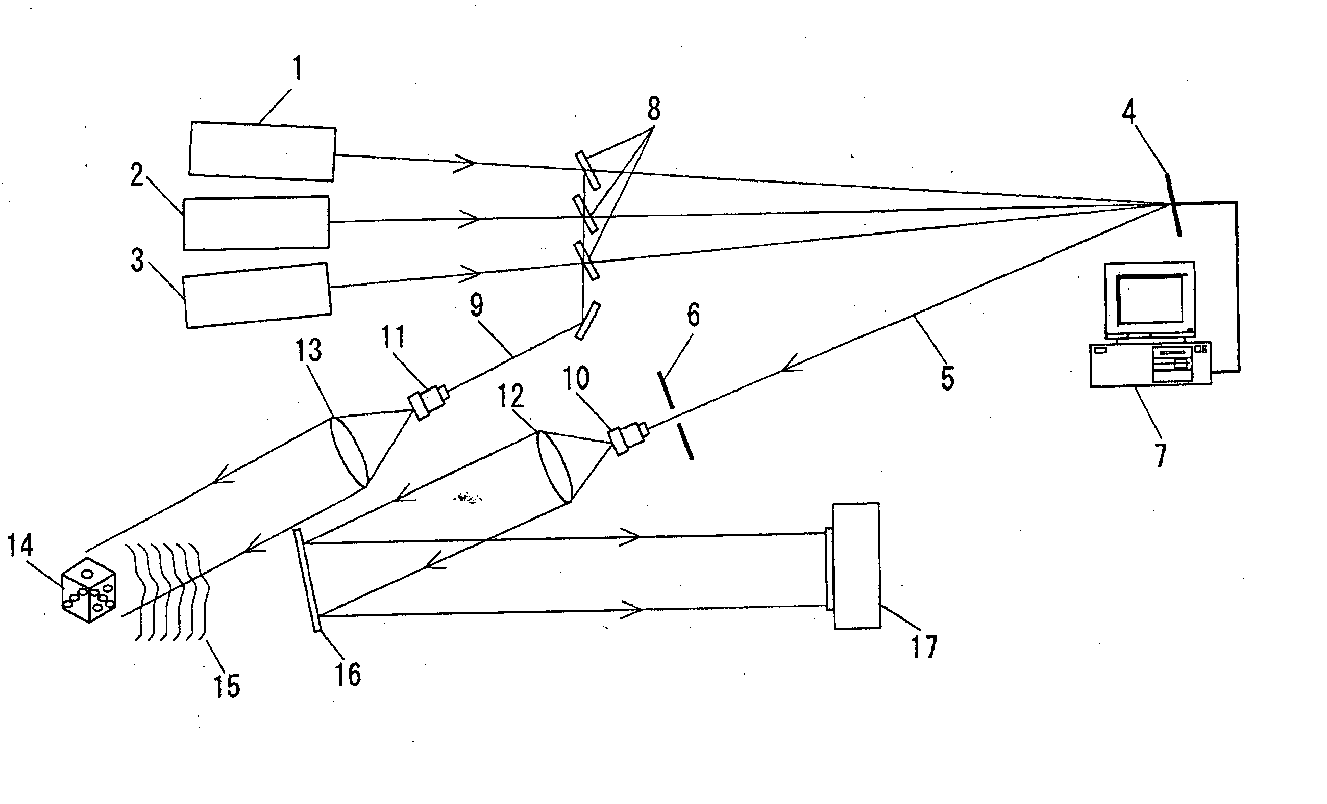
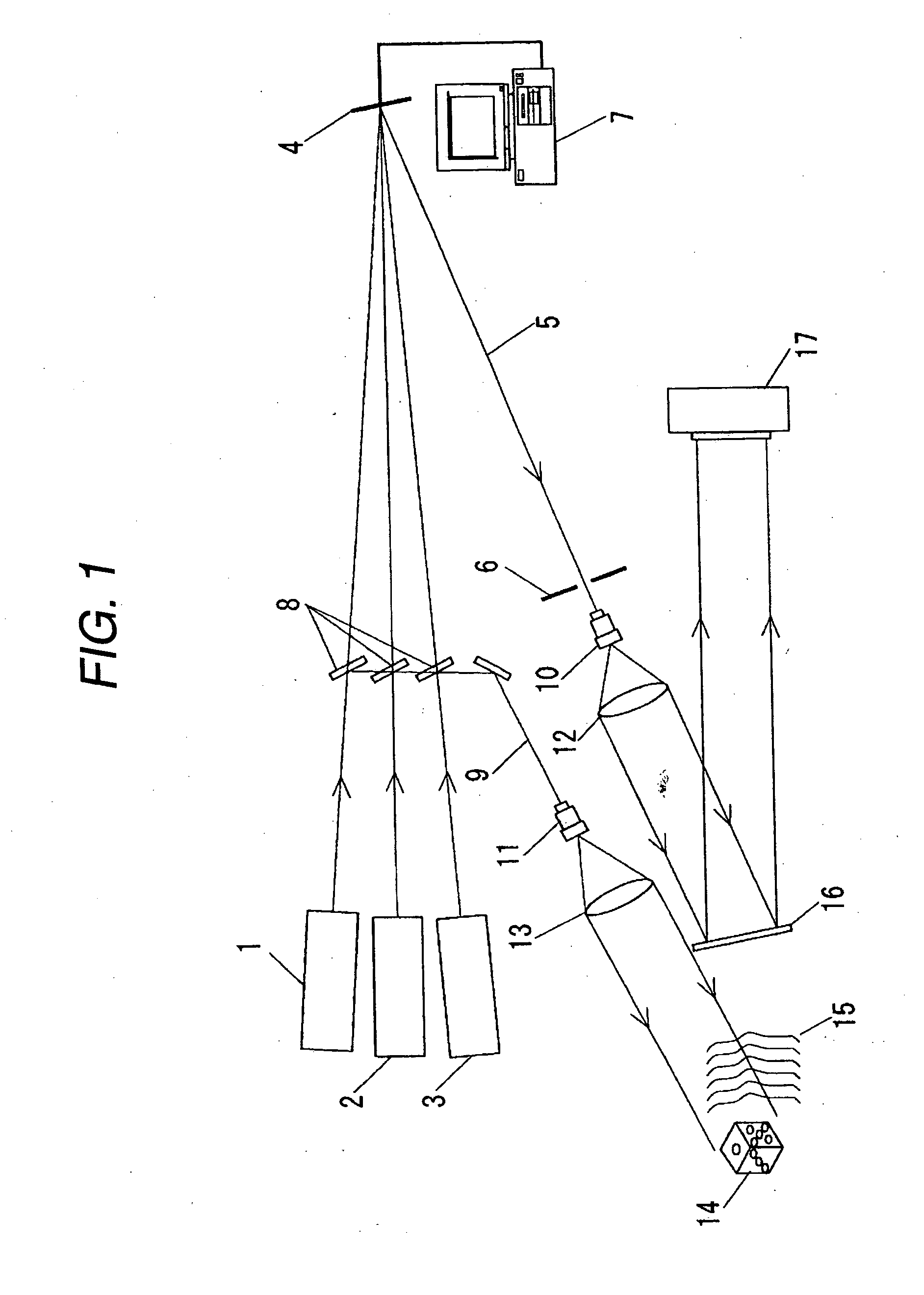
[0020] Hereafter, a description will be given, while referring to FIG. 1 and FIG. 2, of a three-dimensional color image recording apparatus using a phase shift digital holography of the invention.

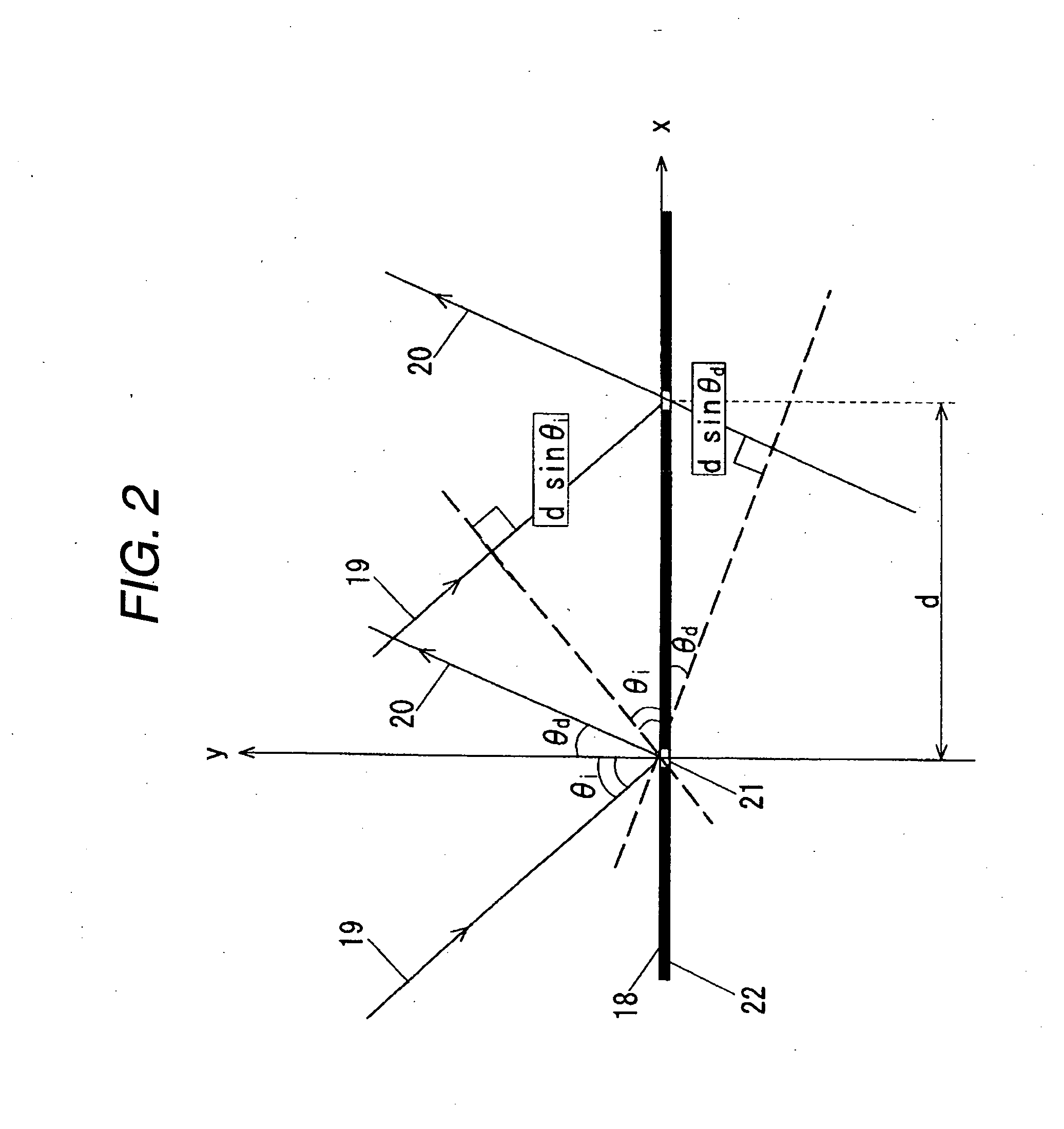
[0021]FIG. 1 is an illustration showing the three-dimensional color image recording apparatus using the phase shift digital holography according to an embodiment of the invention, while FIG. 2 is an illustration of an mth diffracted beam created by a parallel incident beam and a reflective lattice fringe. As a light source for a recording, each laser oscillator of a red laser oscillator 1, a green laser oscillator 2 and a blue laser oscillator 3 is used. A red semiconductor laser with a light wavelength of 650 nm has been used as the red laser oscillator 1, a semiconductor excited green solid-state laser with a light wavelength of 532 nm as the green laser oscillator 2, and a blue semiconductor laser with a light wavelength of 440 nm as the blue laser oscillator 3.

[0022] Laser beams from ...


PUM


Abstract

The invention displays a lattice fringe on a spatial light modulator such as a liquid crystal panel or a digital mirror device panel, irradiates it with laser beams in three primary colors red, green and blue, and uses a primary diffracted beam created by the lattice fringe as an image recording reference beam. On moving the lattice fringe on the spatial light modulator on the modulator, a phase of the diffracted beam shifts due to a movement of a fringe, a phase shift amount of the beam is proportionate to an amount of movement of the fringe, and becomes unconnected to a wavelength of the beam. By this method, as an optical phase can be accurately shifted rendering unnecessary a device for detecting or regulating the optical phase, a system configuration of an image recording apparatus becomes simple.

Description

BACKGROUND OF THE INVENTION [0001] The present invention relates to a color phase shift digital holography which makes possible a three-dimensional display used in an image technology field, an amusement field, an entertainment field, an internet field, an information field, a multimedia field, a communications field, an advertising and publicity field, a medical field, an art field, an education field, a design support field, a simulation field, a virtual reality and the like, as well as an apparatus which records a three-dimensional color image by the phase shift digital holography. In particular, it relates to an apparatus which, having an advantage of being capable of a simultaneous high-speed recording of a color image as a red, green and blue three primary color hologram, records a high-quality three-dimensional color image with a simple system configuration. [0002] To date, in a case of recording a three-dimensional image by a digital holography, when using a light receiving ...

Claims


Application Information

Patent Timeline
IPC IPC(8): G02B26/08
CPCG03H1/0248G03H1/04G03H1/0443G03H2001/0447G03H2001/0458G03H2001/0489G03H2210/13G03H2222/18G03H2225/22
Inventor KUBARA, TAKASHISATO, KUNIHIRO
Owner PANASONIC CORP
Learn More