
Microchip processing apparatus

a technology of microchips and processing equipment, applied in chemical methods analysis, laboratory glassware, instruments, etc., can solve the problems of increasing the size of the reagent container, affecting the analysis results, and affecting the quality of the sample, so as to reduce the damage to the dispensing probe, control the waste of resources, and reduce the effect of waste of resources

Active Publication Date: 2007-05-10
SHIMADZU CORP
View PDF6 Cites 7 Cited by
  • Summary
  • Abstract
  • Description
  • Claims
  • Application Information

AI Technical Summary

Benefits of technology

The present invention provides a microchip processing apparatus that is suitable for handling samples containing minute quantities of samples. The apparatus includes a holding part for holding a microchip with a main separation channel, a dispensing probe for drawing samples or reagents, and a dispensing probe driving mechanism for moving the dispensing probe between prescribed positions on the microchip. The apparatus also includes a seal material that can be penetrated by the dispensing probe, and a restraining mechanism for preventing the dispensing probe from coming up when it is pulled out from the sample container. The invention aims to reduce the wasteful consumption of reagents and samples, and to improve the accuracy and precision of the analysis results.

Problems solved by technology

If due to human error the analysis is continued in a condition when the quantity of separation buffer solution is insufficient, the analytical results will suffer.
If an excess of separation buffer solution is poured into the container to avoid such a situation, wasteful consumption of separation buffer solution will occur, and the size of the reagent container may also increase.
Also, if the analysis is continued in a condition when the quantity of separation buffer solution is insufficient and the analytical results are poor, the sample is wasted.

Method used


Image

  • Microchip processing apparatus
  • Microchip processing apparatus
  • Microchip processing apparatus

Examples


Embodiment Construction

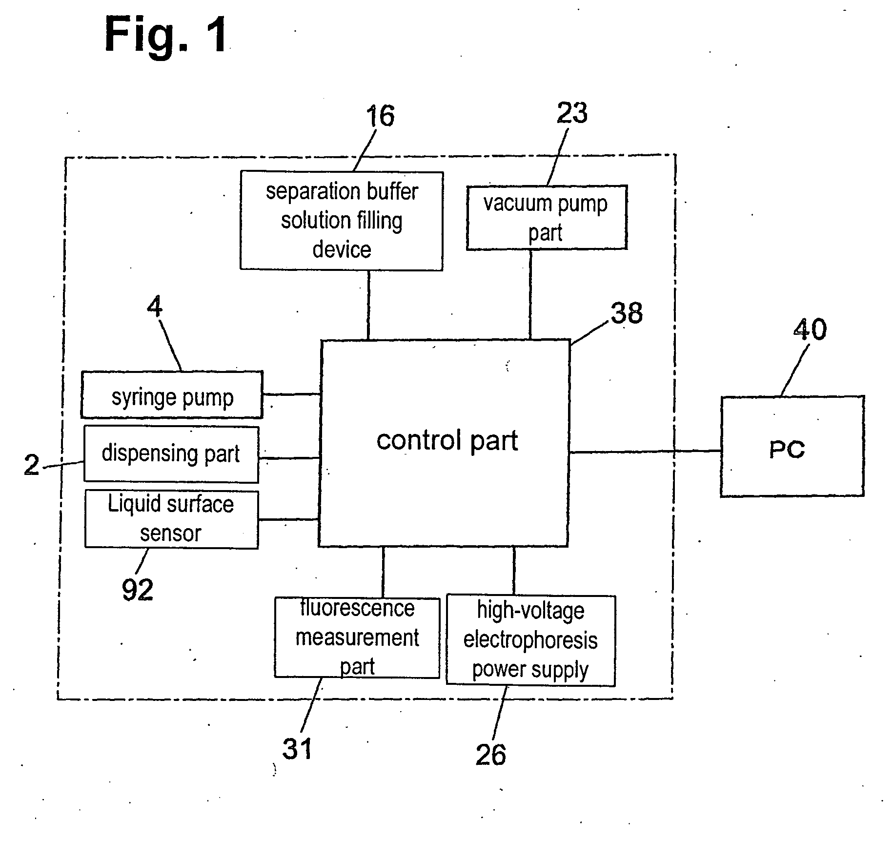
[0067]FIG. 1 is a block diagram of one embodiment of a control part according to one aspect of a microchip electrophoresis apparatus.

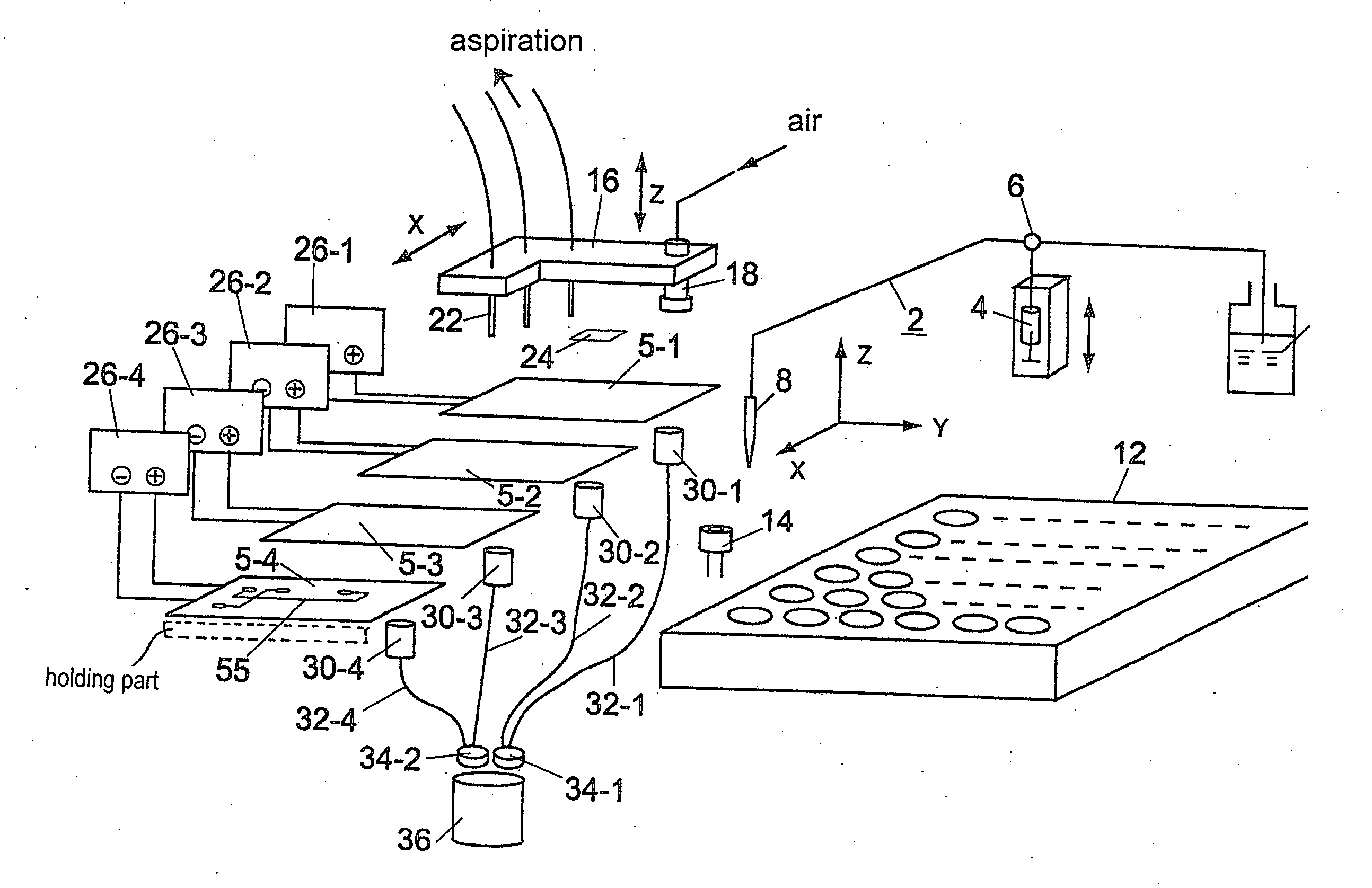
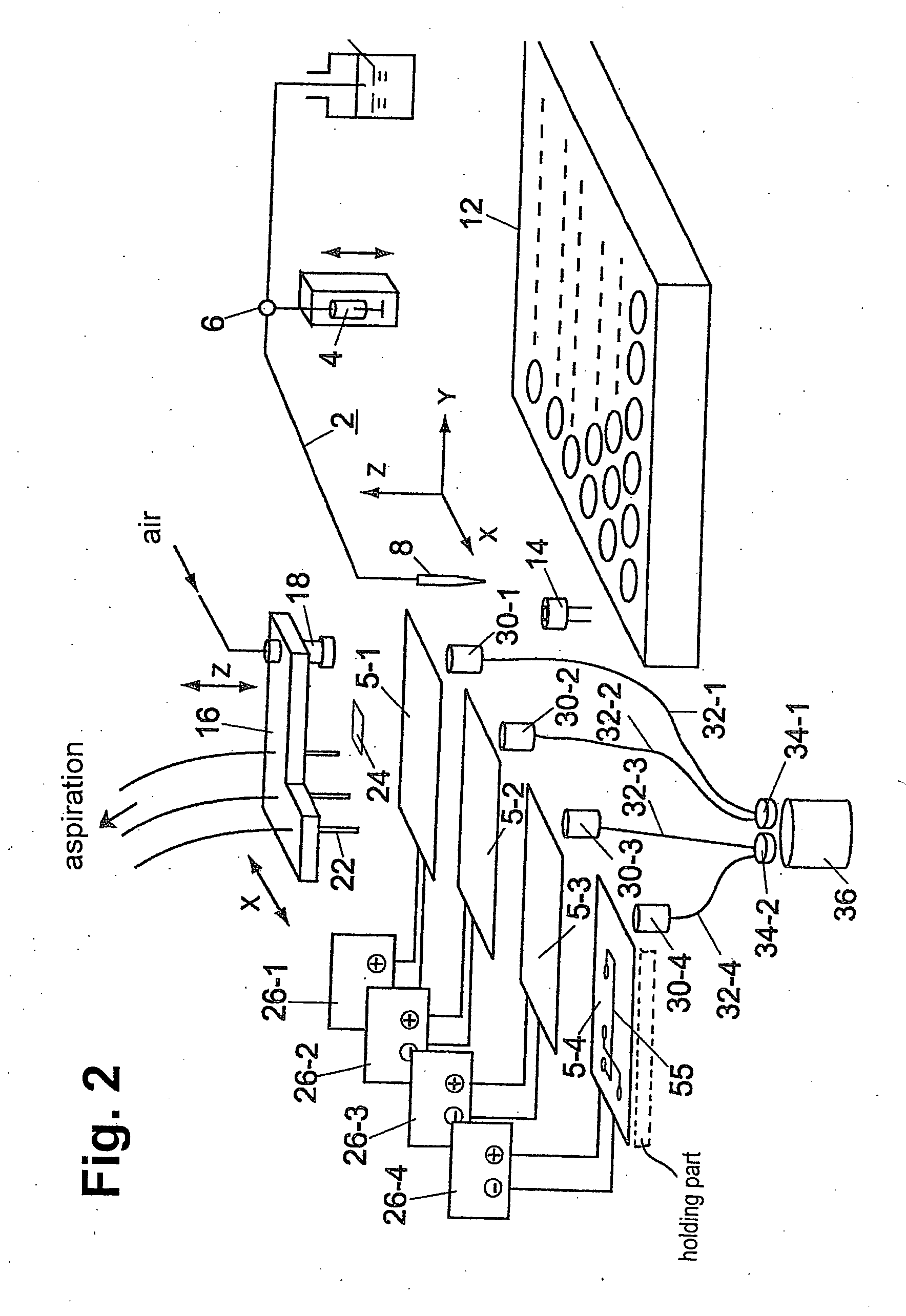
[0068] Dispensing part 2 includes a dispensing probe driving mechanism having a dispensing probe. The dispensing probe of the dispensing part 2 draws in a separation buffer solution or a sample by a syringe pump 4 and injects it to one end of the electrophoresis channel of the microchip. The dispensing probe is common to a plurality of electrophoresis channels. Separation buffer 16 is a solution filling device in which separation buffer solution, injected into one end of the electrophoresis channel, is filled by air pressure into the electrophoresis channel. Superfluous separation buffer solution is discharged by a vacuum pump part 23, and the separation buffer solution filling device 16 is common to the plural electrophoresis channels in order to perform processing.

[0069] In addition, high-voltage electrophoresis power supply 26 applies phoresis vol...


PUM

PropertyMeasurementUnit
timeaaaaaaaaaa
forceaaaaaaaaaa
electrostatic capacitanceaaaaaaaaaa

Abstract

A microchip processing apparatus processes a microchip with at least one main separation channel. The microchip processing apparatus includes a holding part configured to hold the microchip, a container containing a sample or a reagent, and a dispensing probe having a needle formed on a tip of the dispensing probe. The dispensing probe is actuated to be inserted into the container from above the container, to draw the sample or reagent, and to inject to a prescribed position on the held microchip. A dispensing probe driving mechanism moves the dispensing probe between prescribed positions of the microchip and the container.

Description

BACKGROUND OF THE INVENTION AND RELATED ART STATEMENT [0001] The present invention relates to a microchip processing apparatus for performing analysis by a method, such as microchip electrophoresis method and micro liquid chromatography. [0002] The microchip processing apparatus comprises at least a holding part for holding a microchip, the holding part having at least a main separation channel in which analysis is performed while a solution moves inside a plate-like member, a dispensing probe for drawing a sample or a reagent, the probe being inserted from above into a container having a sample or a reagent and injecting to a prescribed position on the microchip held by the holding part, and a dispensing probe driving mechanism for moving the dispensing probe between prescribed positions of the microchip and the container. [0003] In microchip electrophoresis, a sample such as DNA, RNA or protein introduced on one side of a main separation channel is electrophoretically separated to...

Claims


Application Information

Patent Timeline
Patent Type & Authority Applications(United States)
IPC IPC(8): G01N33/00
CPCB01L3/0293B01L3/502715Y10T436/2575B01L2200/143B01L2300/0816B01L2200/027
Inventor HANAFUSA, NOBUHIROSEKI, KATSUHIKONISHIDA, TAIGOSUDO, TOMOKAZUKASHIWAGI, KATSUYA
Owner SHIMADZU CORP
Learn More