Synchronization of ultrasound imaging data with electrical mapping

a technology of ultrasound imaging and electrical mapping, applied in the field of anatomic cardiac imaging and electroanatomical mapping, can solve the problems of cardiac cycle shape changes in the heart chamber, the inability to register the electroanatomical map and the 2-dimensional and 3-dimensional ultrasound images, and the discrepancy between the location of points on the heart wall, so as to achieve greater diagnostic accuracy

Active Publication Date: 2007-05-10
BIOSENSE WEBSTER INC
View PDF18 Cites 222 Cited by
  • Summary
  • Abstract
  • Description
  • Claims
  • Application Information

AI Technical Summary

Benefits of technology

[0008] Both ultrasound imaging and electro-anatomical maps are methods that may be used to diagnose and monitor conditions of the heart, such as ischemia and infarction. When used together, the two monitoring techniques can provide greater diagnostic accuracy than either technique alone. In addition, the two methods can be used in conjunction with ablation to confirm that an intended region has been ablated.

Problems solved by technology

One difficulty that may arise in registering the electro-anatomical map and the 2-dimensional and 3-dimensional ultrasound images is that the shape of the heart chambers changes during the cardiac cycle.
Thus, there may be a discrepancy between the locations of points on the heart wall at which electrical measurements are made and the locations at which these points appear in the ultrasound image.
This discrepancy may cause distortion in the presentation of the electro-anatomical map and confusion in the doctor's interpretation of the information.
Such systems are unable to display 3-dimensional anatomic images concurrently with electro-anatomical maps in realtime.
In the absence of such synchronization, the 3-dimensional image would be hopelessly blurred.

Method used


Image

  • Synchronization of ultrasound imaging data with electrical mapping
  • Synchronization of ultrasound imaging data with electrical mapping
  • Synchronization of ultrasound imaging data with electrical mapping

Examples


example 1

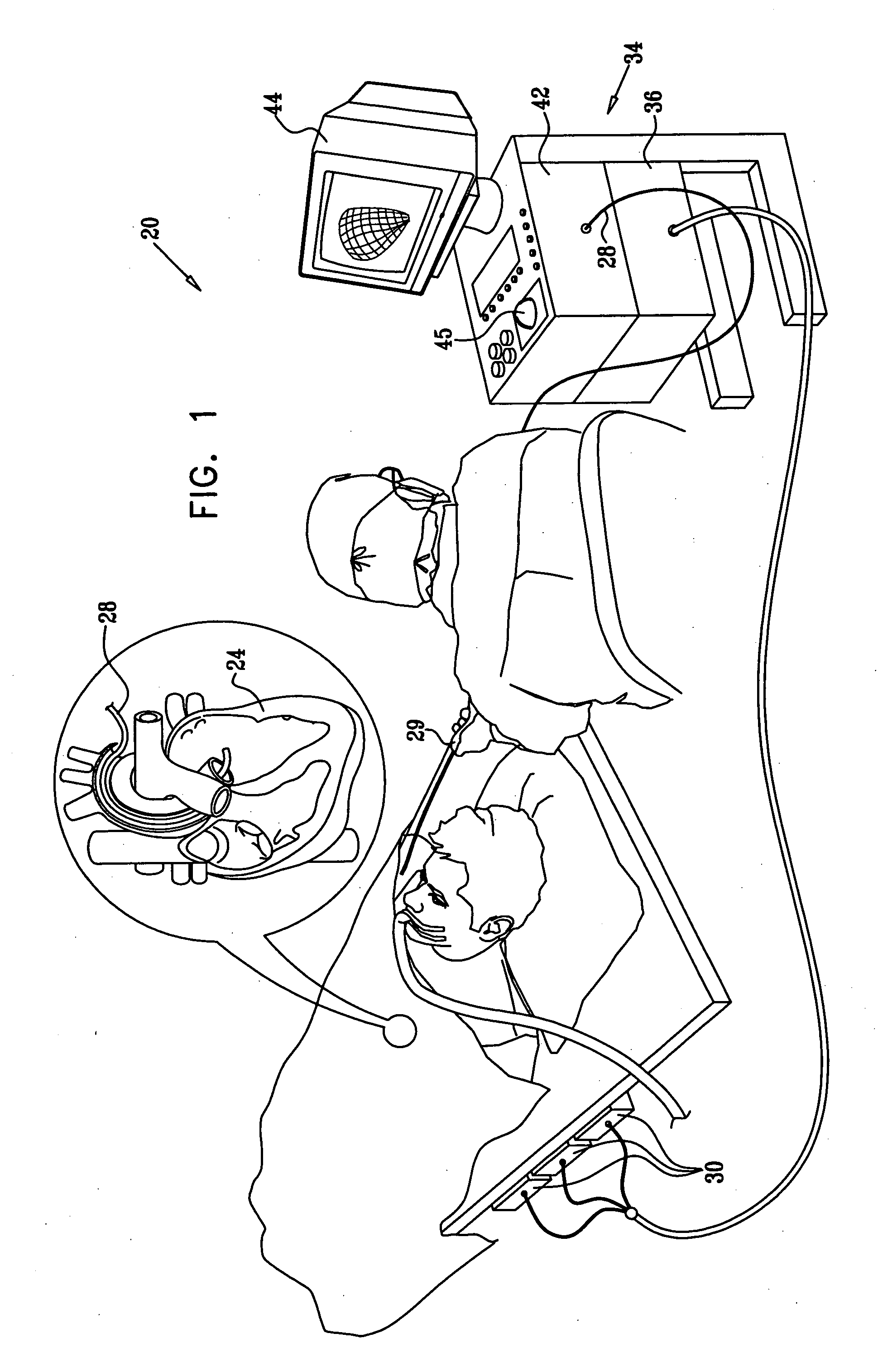
[0110] A Carto XP system, available from Biosense-Webster, was used for producing an electro-anatomical map and for position calculations for the mapping catheter. A Sequoia™ system, available from Siemens Medical Solutions USA, Inc., Ultrasound Division Headquarters P.O. Box 7393 Mountain View, Calif. 94039-7393, was used for acquisition of ultrasound images, in conjunction with an AcuNav™ diagnostic ultrasound catheter, also available from Siemens. The AcuNav catheter was modified by the insertion of a location sensor adjacent to the ultrasound transducer. The location sensor was calibrated together with the ultrasound transducer, enabling the Carto XP system to calculate the position of every pixel in 2-dimensional ultrasound images. A video grabber card was added to the workstation of the Carto XP system. The video output from the Sequoia system was connected to the video grabber card. The ultrasound signals from the AcuNav catheter were connected to the Sequoia system, and the ...

example 2

[0114] Yet another method of establishing a delay is to measure the time interval between the time the position of the catheter was determined and the time at which corresponding image is presented. A time reference is established by generating interference in the ultrasound image using a pulsed RF signal in the imaging frequency (˜7 MHz). The CARTO XP system was triggered at the moment that the interference was produced in order to obtain position data of the catheter. Than a delay in time is determined by the difference between the time at which the catheter position was sampled and the time stap of the image having the interference, as grabbed by the Carto XP system. This interval is then calculated and used as a constant delay.

[0115] Reference is now made to FIG. 13, which is a series of three ultrasound images of the heart acquired at 10 ms intervals in order to establish a delay offset in accordance with a disclosed embodiment of the invention. Data was acquired using the sys...

embodiment 1

[0118] Reference is now made to FIG. 14, which is a flow chart illustrating a method of concurrently displaying two gated images acquired using different modalities, in accordance with a disclosed embodiment of the invention. The process steps are shown in a particular sequence in FIG. 14 for clarity of presentation. However, it will be evident that many of them can be performed in parallel, asynchronously, or in different orders.

[0119] At initial step 160 a first cyclical image is acquired by known techniques. This is a 3-dimensional electro-anatomical map, which can be obtained using the above-described Carto XP system.

[0120] Next, at step 162 a second cyclical image is acquired in near realtime. Typically this is a 3-dimensional ultrasound image of a structure having cyclical motion, such as the heart. However, the second image could be acquired by many other modalities, for example x-ray computed tomography or PET techniques.

[0121] Next, at step 164, a gating point is selecte...


PUM


Abstract

An image of an electro-anatomical map of a body structure having cyclical motion is overlaid on a 3D ultrasonic image of the structure. The electro-anatomical data and anatomic image data are synchronized by gating both electro-anatomical data acquisition and an anatomic image at a specific point in the motion cycle. Transfer of image data includes identification of a point in the motion cycle at which the 3-dimensional image was captured or is to be displayed.

Description

BACKGROUND OF THE INVENTION [0001] 1. Field of the Invention [0002] This invention relates to anatomic cardiac imaging and electro-anatomical mapping. More particularly, this invention relates to synchronized display of 3-dimensional ultrasound images and electro-anatomical maps of the heart. [0003] 1. Description of the Related Art [0004] The meanings of acronyms and certain terminology used herein are given in Table 1. TABLE 1CTComputed Tomography; Computed TomographicECGElectrocardiogramHIFUHigh Intensity Focused UltrasoundIODInformation Object DefinitionMRIMagnetic Resonance ImagingPETPositron Emission Tomography[0005] Methods for three-dimensional geometrical mapping and reconstruction of the endocardial surface are known in the art. For example, U.S. Pat. No. 5,738,096, whose disclosure is incorporated herein by reference, describes methods for mapping the endocardium based on bringing a probe into contact with multiple locations on a wall of the heart, and determining positi...

Claims


Application Information

Patent Timeline
Patent Type & Authority Applications(United States)
IPC IPC(8): A61B5/05A61B8/00
CPCA61B5/042A61B5/06A61B5/7289A61B6/5247A61B6/5288A61B8/12A61B8/4488A61B8/483A61B8/5238A61B8/5284A61B5/0035A61B5/062A61B5/283A61B8/00
Inventor ALTMANN, ANDRES CLAUDIOGOVARI, ASSAF
Owner BIOSENSE WEBSTER INC
Why Eureka
Try Eureka