Electronic circuits to improve the sensitivity of magnetic resonance tracking catheters and intraluminal RF coils

Inactive Publication Date: 2007-05-10
GENERAL ELECTRIC CO
View PDF25 Cites 27 Cited by
  • Summary
  • Abstract
  • Description
  • Claims
  • Application Information

AI Technical Summary

Benefits of technology

[0018] An embodiment may also comprise a method for improving the sensitivity of and for reducing the adverse heating effects of an invasive probe having an inductor coil used in detecting magnetic resonance imaging (MRI) resonant signals comprising: providing a cable connected to an inductor coil wherein the cable has an effective electrical length set to be an odd multiple of λ/4 where λ is the wavelength of a known RF high power pulse signal used during an

Problems solved by technology

For interventional procedures, the issue of patient isolation is more complicated since interventional devices are in contact with the subject.
Prior art receive coils have, under certain conditions, had problems tuning the frequency of the receive rf coil to the Larmor frequency of the nuclei.
In general, the greater the distance between the coil and body, the poorer the MRI image.
Permanent magnets or conventional electromagnets can produce fields which often vary with time due to temperature variations, resulting in changes in the resonance frequency.
Such drifts result in the coil being severely detuned with respect to the Larmor frequency of the MRI system, leading to poor signal-to-noise ratios and, hence, poor image quality.
These currents

Method used


Image

  • Electronic circuits to improve the sensitivity of magnetic resonance tracking catheters and intraluminal RF coils
  • Electronic circuits to improve the sensitivity of magnetic resonance tracking catheters and intraluminal RF coils
  • Electronic circuits to improve the sensitivity of magnetic resonance tracking catheters and intraluminal RF coils

Examples


Example

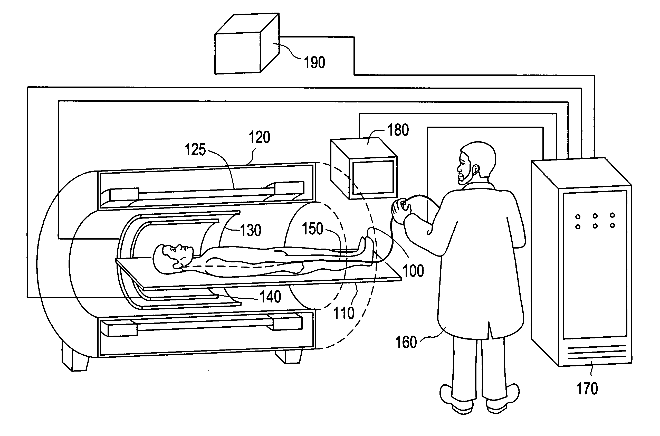
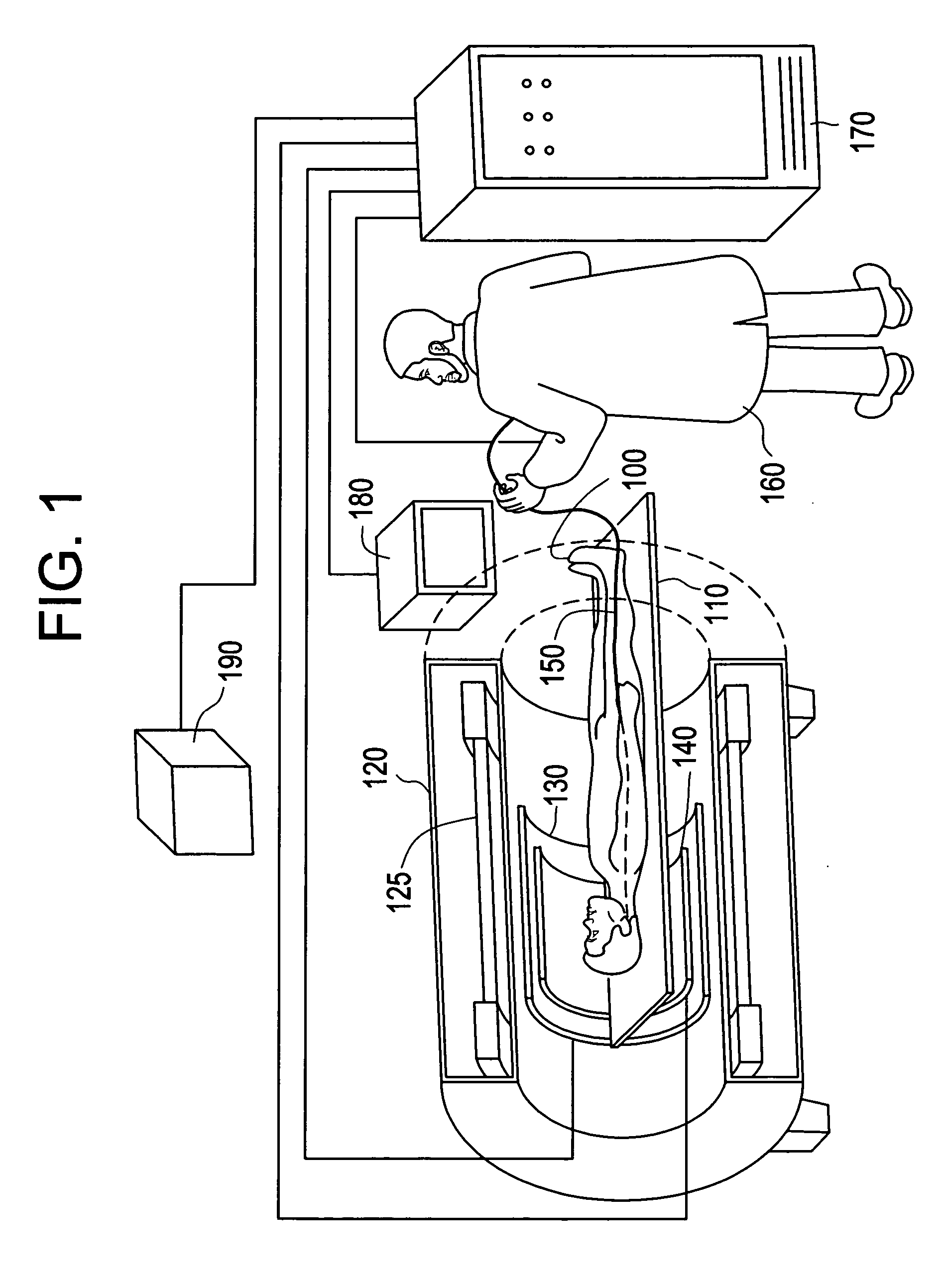
[0029] In FIG. 1, a subject 100 on a support table 110 is placed in a homogeneous magnetic field generated by a magnet 125 in magnet housing 120. Magnet 125 and magnet housing 120 have cylindrical symmetry and are shown sectioned in half to reveal the position of subject 100. A region of subject 100 into which a device 150, shown as a catheter, is inserted, is located in the approximate center of the bore of magnet 125. Subject 100 is surrounded by a set of cylindrical magnetic field gradient coils 130 (shown sectioned in half) which create magnetic field gradients of predetermined strength at predetermined times. Gradient coils 130 generate magnetic field gradients in three mutually orthogonal directions.

[0030] An external coil 140 also surrounds a region of interest of subject 100. Coil 140 is shown (sectioned in half) as a cylindrical external coil which has a diameter sufficient to encompass the entire subject. Other geometries, such as smaller cylinders specifically designed f...


PUM


Abstract

Devices, methods, and articles of manufacture related to an invasive device for inserting an inductor coil proximate to a specimen for detecting magnetic resonance imaging (MRI) resonant signals from the specimen; a conductor for conducting a signal from the inductor coil wherein the conductor has an effective electrical length set to be an odd multiple of λ/4 where λ is the wavelength of a known frequency of an electromagnetic signal presented to the conductor.

Description

FIELD OF THE INVENTION [0001] This invention relates to the field of magnetic resonance imaging (MRI) and in particular, to an invasive interventional device such a guidewire, wire, or catheter for use with a magnetic resonance imaging (MRI) scanner. BACKGROUND OF THE INVENTION [0002] Many conventional medical procedures involve imaging of internal organs of a subject during a medical procedure in order to guide a physician around structures such as vessels, and nerves. [0003] There are also invasive medical procedures in which a device, such as a catheter has a radiofrequency (RF) coil incorporated in it for the purpose of acquiring magnetic resonance (MR) signals to be used either for locating the catheter and / or providing an MR image. [0004] Patients undergoing medical imaging must be protected from failures of the medical imaging apparatus and other medical equipment connected to the patient. Due to the nature of magnetic resonance (MR) imaging, special requirements exist. In no...

Claims


Application Information

Patent Timeline
IPC IPC(8): A61B5/05
CPCA61B5/055A61B5/064A61B5/6857G01R33/287G01R33/3657
Inventor DUMOULIN, CHARLES LUCIAN
Owner GENERAL ELECTRIC CO
Why Eureka
Try Eureka