Motor-driven supercharger

a supercharger and motor technology, applied in the direction of machines/engines, mechanical equipment, electric generator control, etc., can solve the problems of large power loss and enlarged size of the inverter, and achieve the effect of reducing power loss

Active Publication Date: 2007-05-17
IHI CORP
View PDF25 Cites 28 Cited by
  • Summary
  • Abstract
  • Description
  • Claims
  • Application Information

AI Technical Summary

Benefits of technology

[0016] The present invention is made for solving the problem mentioned above. In other words, an object of the present invention is to provide a mo

Problems solved by technology

However, since the electric power after converted by the inverter is the ac power, there is a problem that a great power loss is generated due to an electric resistance and an inductance of a power supply cable connecting the inverter and the motor-driven supercharger.
Accordingly, part

Method used


Image

  • Motor-driven supercharger
  • Motor-driven supercharger
  • Motor-driven supercharger

Examples


Embodiment Construction

[0037] A description will be given below of a preferable embodiment in accordance with the present invention with reference to the accompanying drawings. In this case, the same reference numerals are attached to the common portions in each of the drawings, and an overlapping description will be omitted.

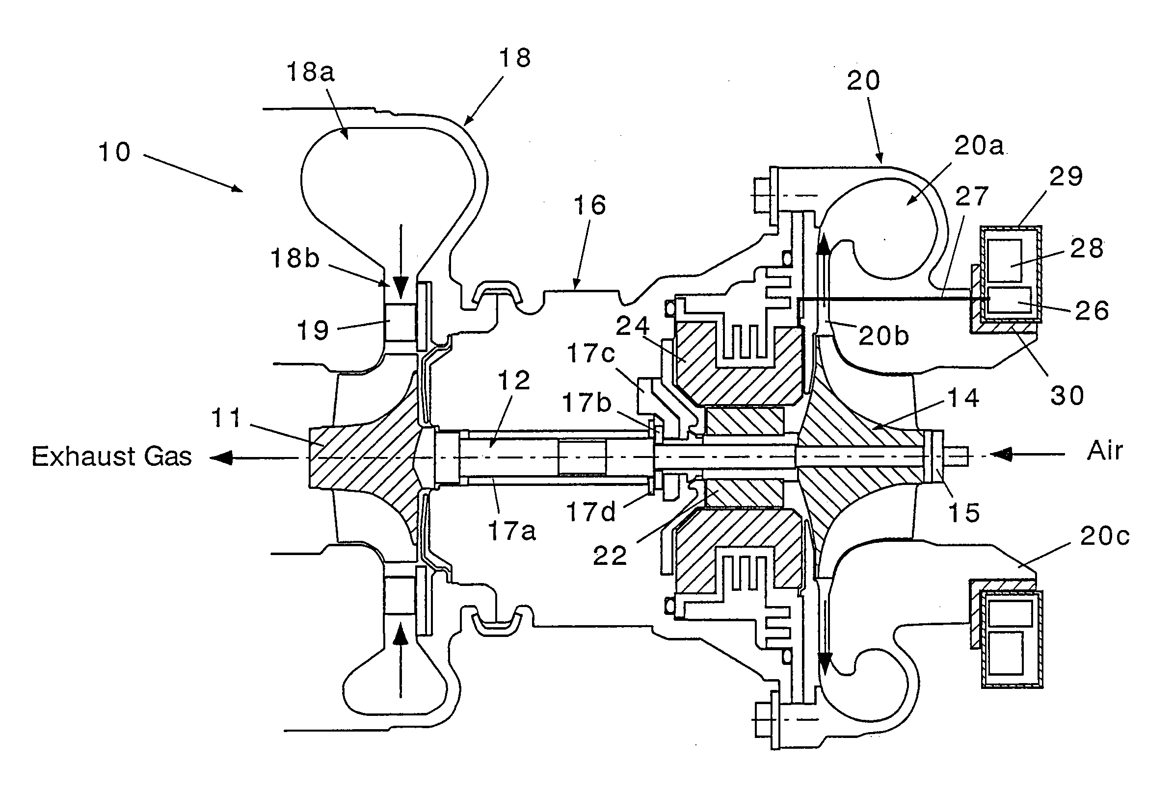
[0038]FIG. 3 is a view of an entire structure of a motor-driven supercharger in accordance with the present invention. In this drawing, a motor-driven supercharger 10 in accordance with the present invention is provided with a turbine shaft 12, a compressor impeller 14, a bearing housing 16, a turbine housing 18 and a compressor housing 20.

[0039] The turbine shaft 12 has a turbine impeller 11 in one end (a left end in the drawing). In this embodiment, the turbine impeller 11 is integrally formed in the turbine shaft 12. However, the present invention is not limited to this, but may be structured such that the turbine impeller 11 is independently attached.

[0040] The compressor impel...


PUM


Abstract

There are provided with a motor rotor (22) fixed to a turbine shaft (12) and rotating together with the turbine shaft, a motor stator (24) surrounding the motor rotor and fixed within a bearing housing (16), an inverted (26) converting a dc power into an ac power, and an inverter controller (28) controlling a frequency and a voltage of the ac power by the inverter. The inverter and the inverter controller are accommodated in a driver container (29), and are coupled to a compressor housing (20) by an insulating coupling member (30).

Description

BACKGROUND OF THE INVENTION [0001] 1. Field of the Invention [0002] The present invention relates to an exhaust turbine supercharger, and more particularly to a motor-driven supercharger having an electric motor built-in. [0003] 2. Description of Related Art [0004] To supply an air having a density increased by a compressor to an engine is called supercharging, and a structure providing for a driving work of the compressor on the basis of an exhaust energy is called as an exhaust-gas turbocharger. [0005] The exhaust-gas turbocharger is generally constituted by a compressor and a turbine which are arranged so as to position a bearing unit therebetween. The compressor has a compressor impeller built-in, and the turbine has a turbine impeller built-in, respectively. The compressor impeller and the turbine impeller are coupled to each other by a connecting shaft supported by a bearing unit, and are structured such as to rotationally drive the turbine impeller by an exhaust gas of the en...

Claims


Application Information

Patent Timeline
IPC IPC(8): F01D15/10H02K7/18H02P9/04
CPCF01D15/10F01D25/14F02B37/10F02B39/10F02B39/16Y02T10/144F05D2220/40F05D2250/70F05D2260/20Y02T10/12
Inventor SHIBUI, YASUYUKITAKAHASHI, YUKIOTOJIMA, NARIFUMI
Owner IHI CORP
Why Eureka
Try Eureka