Regulator circuit
a regulator circuit and regulator technology, applied in the direction of electric variable regulation, process and machine control, instruments, etc., can solve the problems of unnecessary operating current flow and power consumption
- Summary
- Abstract
- Description
- Claims
- Application Information
AI Technical Summary
Benefits of technology
Problems solved by technology
Method used
Image
Examples
Embodiment Construction
[0019] A regulator circuit according to an embodiment of this invention will be explained hereafter referring to the drawings.
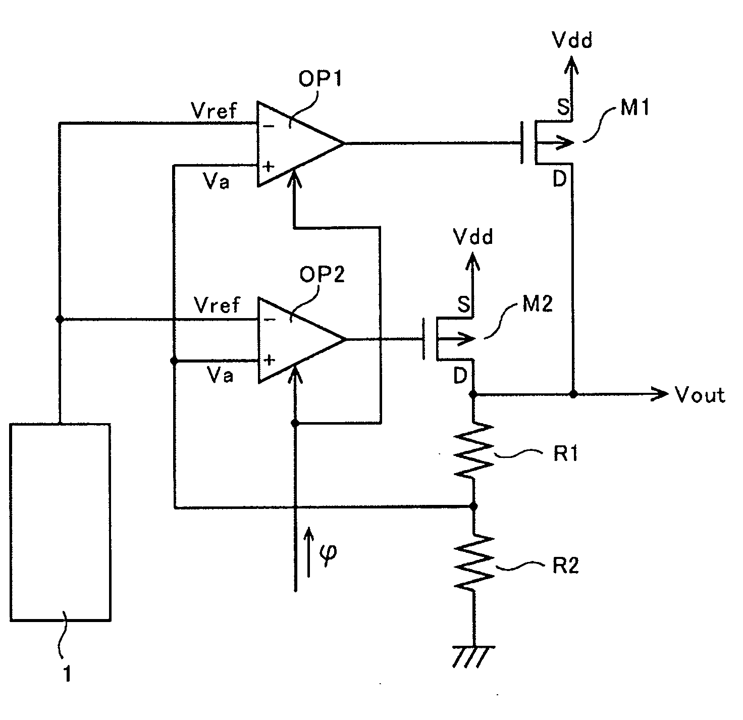
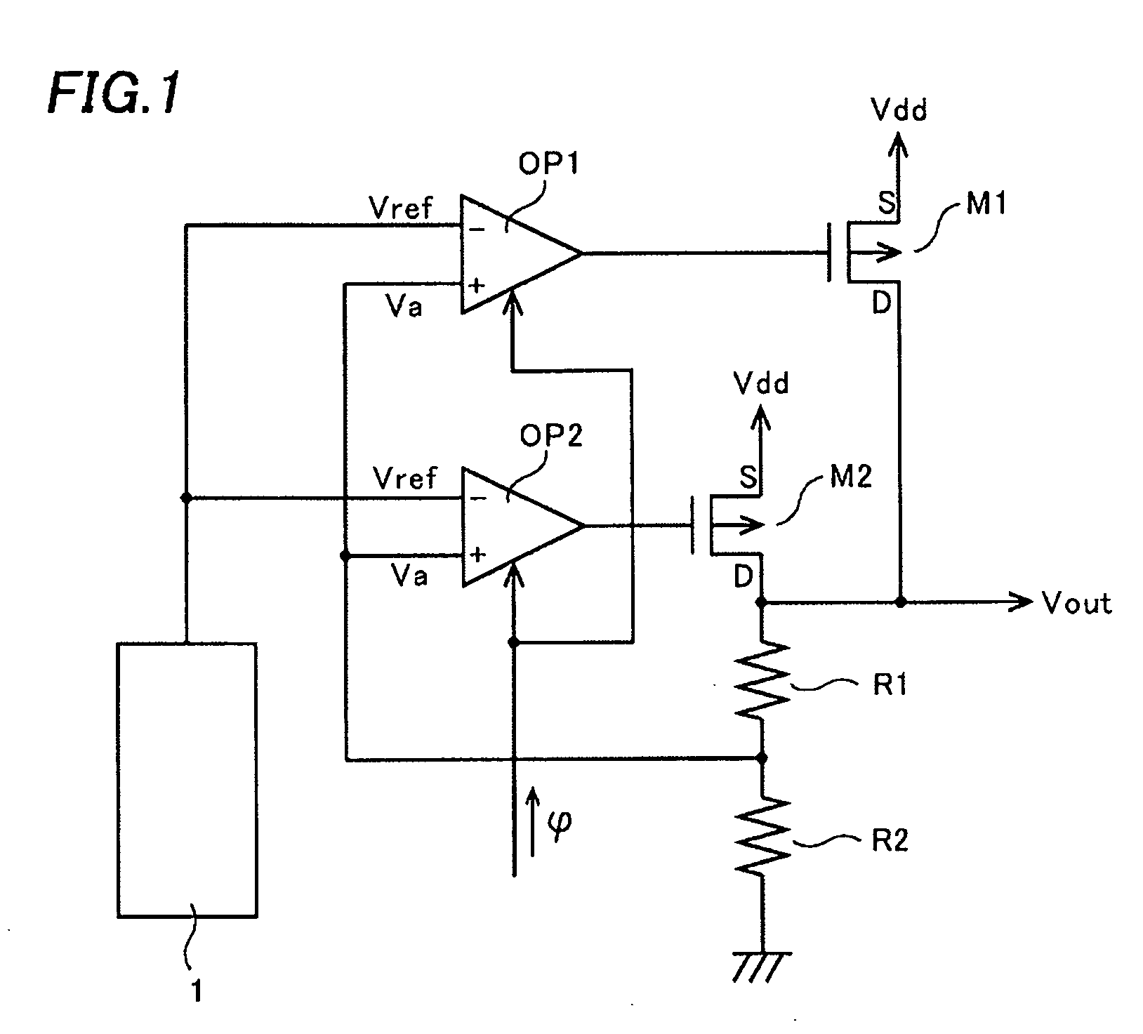
[0020]FIG. 1 shows an example of a circuit structure of the regulator circuit according to the embodiment of this invention. The regulator circuit is provided with a first control MOS transistor M1 of P-channel type having a source to which a power supply voltage Vdd is applied, a first resistor R1 and a second resistor R2 connected in series with a drain of the first control MOS transistor M1, and an operational amplifier OPI having a differential input terminal (−) to which a reference voltage Vref is applied and another differential input terminal (+) to which a voltage Va at a connecting node between the first resistor R1 and the second resistor R2 is applied and applying its output to a gate of the first control MOS transistor M1.
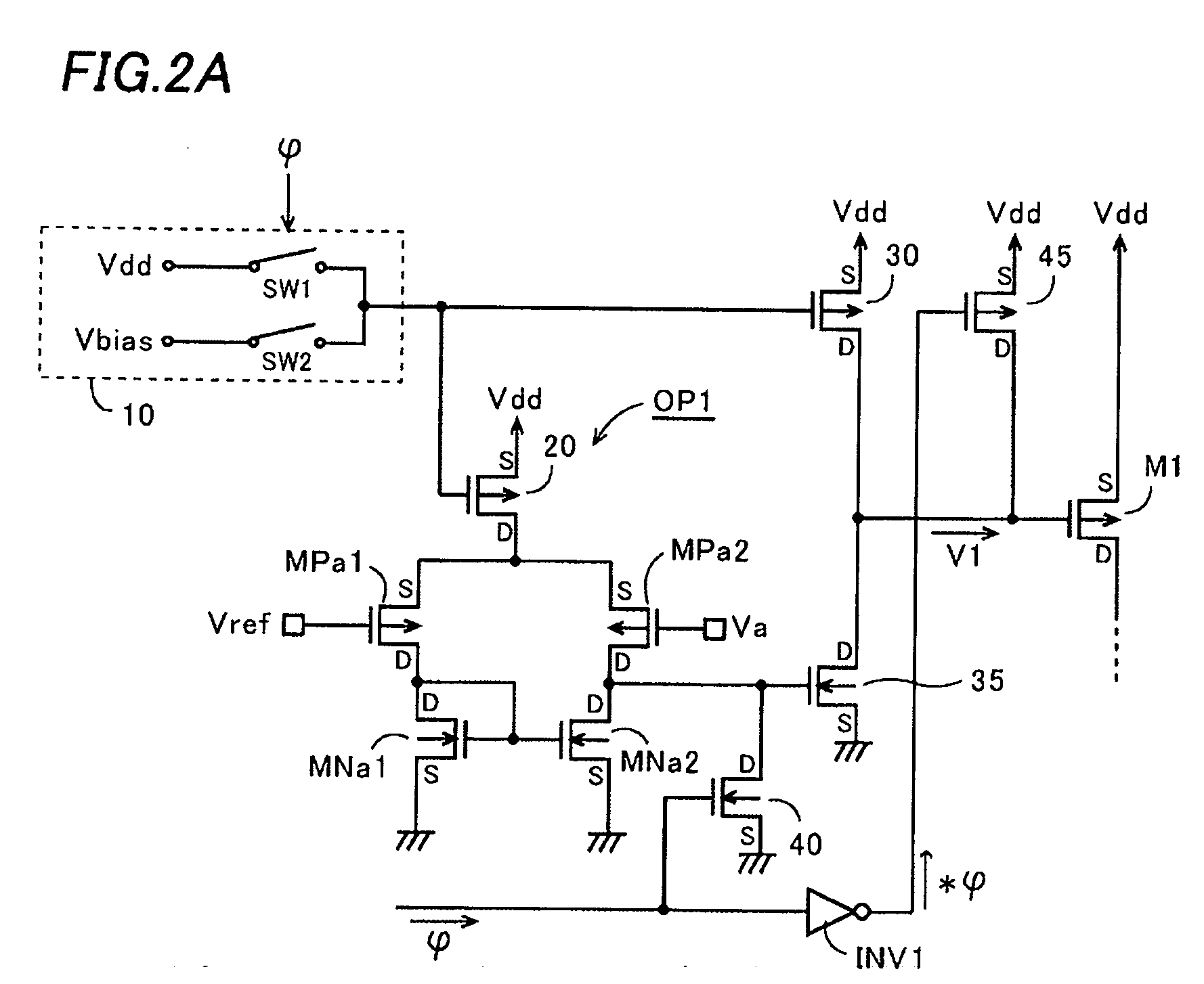
[0021] In this embodiment, the size of an output transistor in the first operational amplifier and the size of the first con...
PUM
 Abstract
Description
Claims
Application Information
 - R&D
- Intellectual Property
- Life Sciences
- Materials
- Tech Scout
- Unparalleled Data Quality
- Higher Quality Content
- 60% Fewer Hallucinations
Browse by: Latest US Patents, China's latest patents, Technical Efficacy Thesaurus, Application Domain, Technology Topic, Popular Technical Reports.
© 2025 PatSnap. All rights reserved.Legal|Privacy policy|Modern Slavery Act Transparency Statement|Sitemap|About US| Contact US: help@patsnap.com


