Mixer Assembly

a technology of mixing and assembly, which is applied in the direction of combustion types, separation processes, lighting and heating apparatuses, etc., can solve the problems of inhomogeneity along the flow profile, inability to achieve any desired compact construction, and inability to meet the requirements of mixing and making available such fuel-air mixtures. , to achieve the effect of increasing the risk of spontaneous ignition, high integratability, and uniform velocity profil

Inactive Publication Date: 2007-05-24
ANSALDO ENERGIA SWITZERLAND AG
View PDF15 Cites 31 Cited by
  • Summary
  • Abstract
  • Description
  • Claims
  • Application Information

AI Technical Summary

Benefits of technology

[0011] One of numerous aspects of the present invention involves forming a mixer assembly for forming a fuel-air mixture which is combinable with a burner system of a heat engine, especially a gas turbine plant, in such a way that producing a fuel-air mixture of high-performance gas turbine applications is possible without having to accept the aforementioned disadvantages of the prior art. It is especially advantageous to make available a large mass flow of a fuel-air mixture, wherein during the whole mixing no flow separations, which cause pressure zones, backflow zones, or dead water zones, are to occur along the flow passages inside the mixer assembly. It is also advantageous to avoid any regions inside the mixer assembly in which regions of increased risk of spontaneous ignition are formed by local fuel accumulations. Furthermore, the fuel-air mixture which is made available by the mixer assembly is preferably suitable for firing a catalytic burner, i.e., the mixture flow advantageously has, as far as possible, a largely uniform velocity profile along the flow cross section. Finally, the mixer assembly is preferably formed as compact and small in construction as possible in order to achieve a high integratability and also the possibility of retrofittability, i.e., retrofittability to burner systems which already exist.
[0012] Another aspect of the present invention includes a method by which the efficient production of a fuel-air mixture for the operation of high performing modern gas turbines is possible.
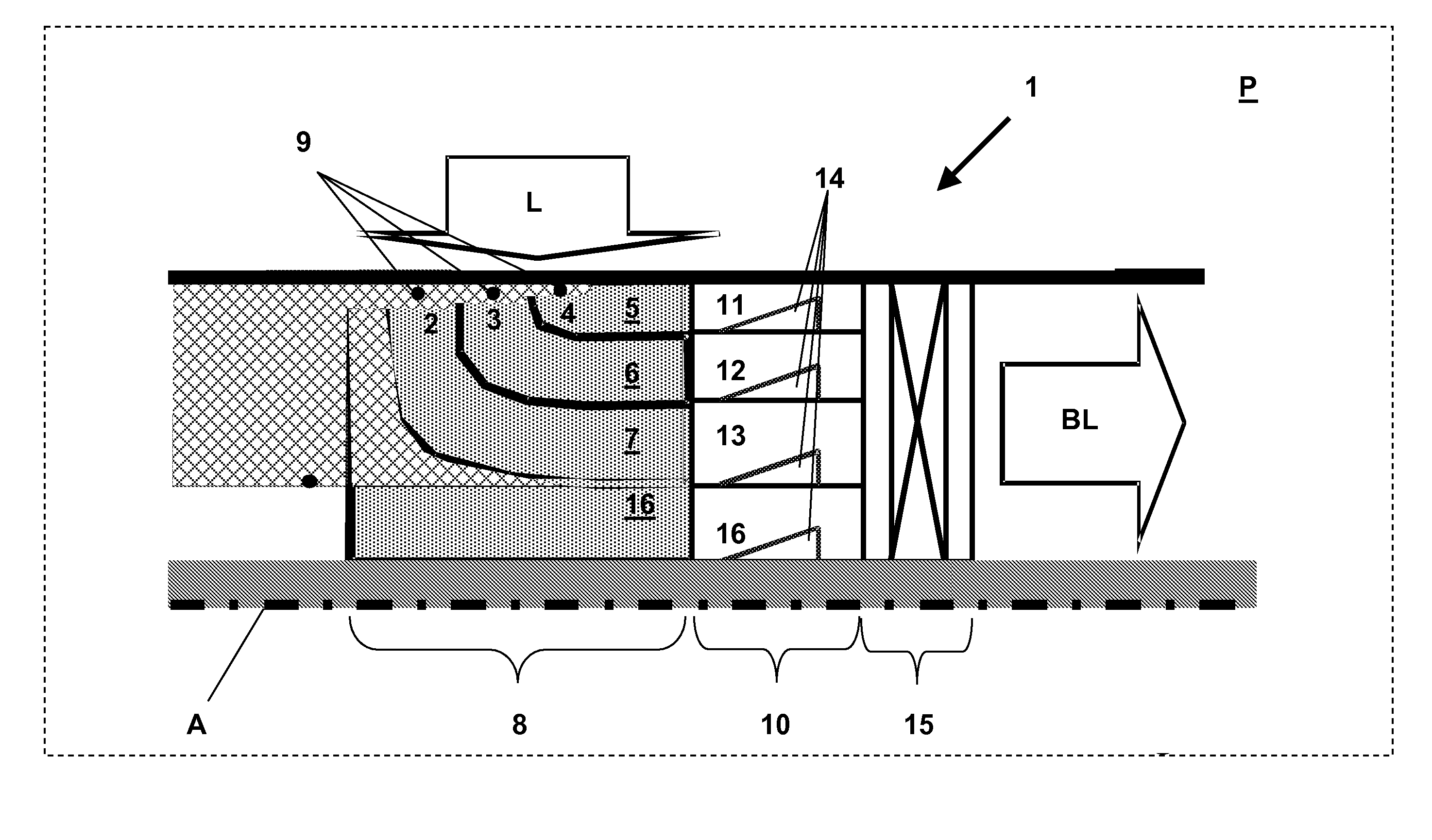
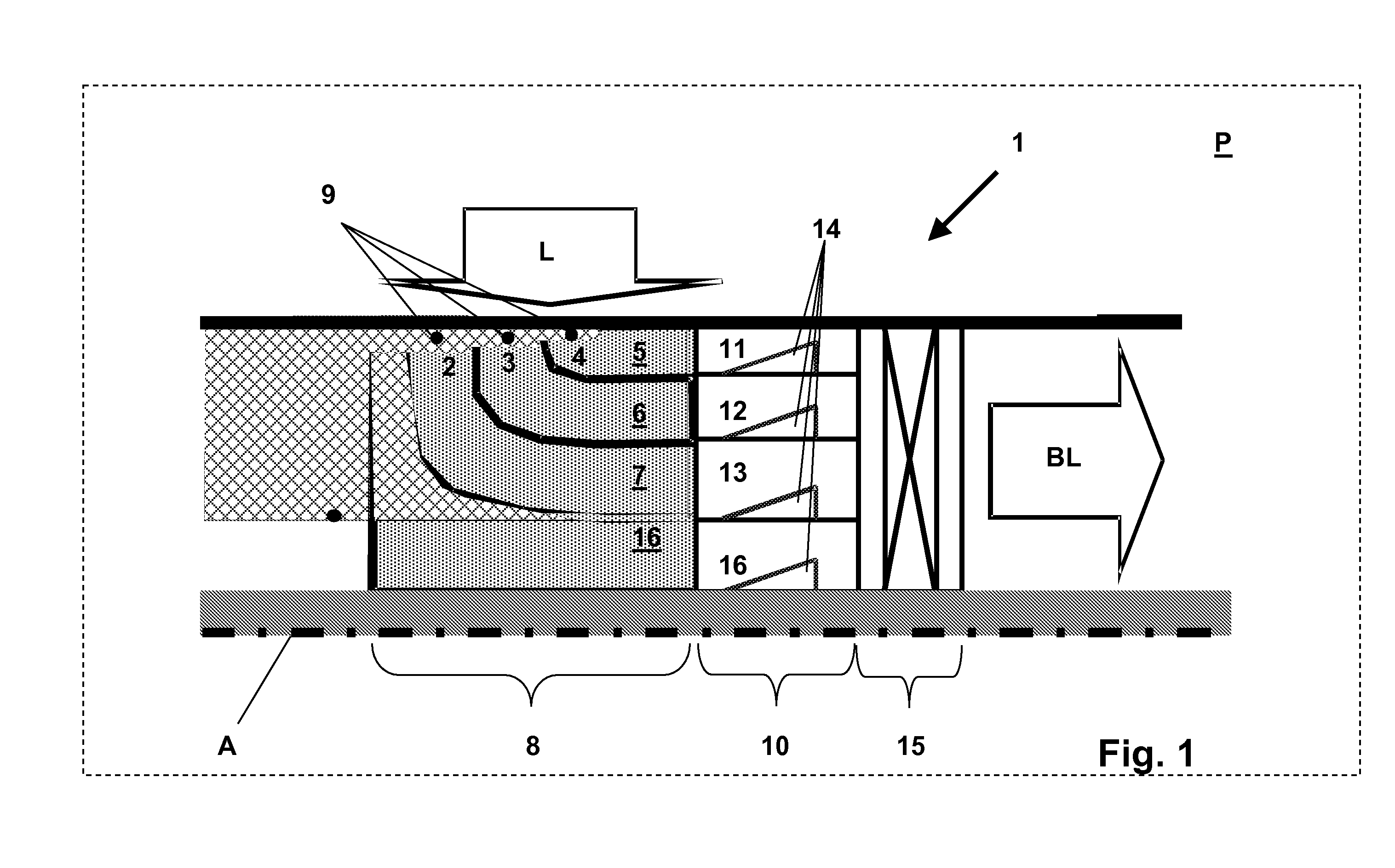
[0016] In order to improve the degree of mixing of the partial flows of fuel-air mixture which are formed along the flow passage sections, an alternative exemplary embodiment of the mixer assembly provides an after-mixing region which is connected downstream directly to the flow deflecting region and which has individual mixing passage sections which are connected downstream flush to the flow passage sections in each case, and in which the respective partial flows of fuel-air mixture experience a further mixing. A flow vortex generating structure, which is introduced into each mixing passage section, serves for this purpose in each case, by means of which, without pressure loss if possible, a strong swirling is induced of the partial flow which passes through the individual mixing passage sections in each case. The individual mixing passage sections have an outlet opening in each case in such a way that the partial flows which emerge from the mixing passage sections are concentrated into a spatially compactly uniform total flow which, in this form, leaves the mixer assembly. The fuel-air mixture which is produced in this way is then fed directly to a burner system, if necessary to a catalytically supported burner system.
[0017] A further exemplary embodiment, instead of the mixing passage sections which are provided with flow vortex generating structures, provides a so-called fine mixing region which is assembled from a number of individual flow passages which are arranged in each case along concentric annular sections and have flow cross sections with flow passage diameters of between 0.5 and 5 mm. Moreover, the individual flow passages per annular section are set at an angle of incidence ±δ to the flow direction by which the fuel-air mixture leaves the flow deflecting region, i.e., all flow passages, which are located in a coaxial annular section, are arranged parallel to each other; however, the flow passage longitudinal axes between two radially adjacent annular sections are located alternately by +δ or −δ in each case, in order to create in this way, downstream of the fine mixing structure, strongly tangentially acting shear forces between the individual flow regions emerging from the annular sections, in order to optimize the degree of mixing through of the fuel-air mixture. Furthermore, the multiplicity of flow passages which are divided into the annular sections act with homogenizing effect on the flow direction, i.e., the flow which emerges from the fine mixing structure experiences a spatial flow concentration which ultimately also affects the axial velocity profile with unifying effect. A further advantage of the fine mixing structure, moreover, is that on account of the only small flow passage cross sections in the millimeter range and below, any risk of a backflash in the course of quenching can be excluded by the fine mixing structure.
[0023] Methods embodying principles of the present invention enable the forming of a fuel-air mixture which propagates along a propagation axis and is homogenously mixed through over the whole flow cross section, and which, in addition, has an isokinetic flow profile which, in a preferred way, is usable for catalytically operable burner systems. By means of the separation, according to the present invention, of the available air flow into at least two, preferably three or four partial flows, which are to be separately deflected, it is possible to effect the deflection of the partial flows largely loss free, i.e., without pressure losses and flow separations in the region of the deflecting zones so that directly downstream of the flow deflecting region each individual partial flow has an isokinetic flow profile which are formed identically to each other in each case. The following measures serve ultimately for the optimization and homogenization of the degree of mixing.
[0024] A flow deflection by a deflection angle β of 90O has proved to be especially advantageous, especially as in this case, in a flow-through component which is formed rotationally symmetrically, an air flow which is directed radially onto the flow-through component can be deflected into an axially oriented air flow. This enables an unusually compact flow guiding inside the mixer assembly and, moreover, allows the retrofitting to burner systems which already exist.

Problems solved by technology

To date, only unsatisfactory solutions for mixing and making available such fuel-air mixtures are known, as they are gatherable, for example, from an article by R. L. Hack et al., “Design and Testing of a Unique, Compact Gas Turbine Catalytic Combustor Premixer”, Proceedings of ASME Turbo Expo 2003, Paper No.
The mixer assemblies which are described in the aforementioned article, however, are only suitable for requirements of low burner capacity, especially as the flow deflecting contours at increased flow velocities, especially in regions of small curvature radii, lead to flow separations close to the passage wall, as a result of which flow regions with flow reversal are created, which ultimately lead to inhomogeneities along the flow profile.
Furthermore, the double curvature along the air feed passage does not allow any desired compact construction which would be desirable, however, for reasons of an integration into a high-performance gas turbine plant.
Considerable mass flows of a homogenous, mixed through fuel-air mixture have to be fed to such plants, which requires high flow velocities at which flow separations are unavoidably established, especially in the region downstream of the passage contours which deflect the flow by 180O, which flow separations, however, it is necessary to avoid.

Method used


Image

  • Mixer Assembly
  • Mixer Assembly
  • Mixer Assembly

Examples


Embodiment Construction

[0032] The mixer assembly, which is schematically shown in FIG. 1, shows the upper half of a flow-through component 1, which is otherwise rotationally symmetrically formed, which is intersected by an axis A. It is assumed that the mixer assembly, which is formed as a flow-through component 1, is located inside a plenum P into which is injected air which is compressed by means of a compressor unit (not shown), which air flows basically radially to the axis A through air inlet openings 2, 3, 4 into the flow-through component. Flow passage sections 5, 6, 7 are connected directly downstream to the air inlet openings 2, 3, 4, along which flow passage sections the partial flows are deflected by 90O from their originally radially oriented flow direction. The flow deflecting region 8, therefore, is able to distribute the total air flow L, which acts radially upon the flow-through component 1, both into partial flows and also to deflect it by 90O into an axially oriented flow direction. For ...


PUM

PropertyMeasurementUnit
flow diameteraaaaaaaaaa
diametersaaaaaaaaaa
diametersaaaaaaaaaa

Abstract

A mixer assembly and a method for forming a fuel-air mixture is combinable with a burner system of a heat engine, especially a gas turbine plant. A flow-through component (1) provides a flow deflecting region (8) which provides at least two air inlet openings (2, 3, 4) to which is each connected a flow passage section (5, 6, 7), which flow deflecting region deflects the airflow which enters the respective flow passage section (5, 6, 7) by a deflection angle β≠0O, and each has an outlet opening, and that a mixing passage section (11, 12, 13) is connected to each of the outlet openings of the flow passage sections (5, 6, 7), in each of which mixing passage section is provided at least one flow vortex generating structure (14), and which each provides an outlet opening; or that a fine mixing region (15) is connected to the outlet openings of the flow passage sections (5, 6, 7), which fine mixing region has a multiplicity of individual flow passages (23) which, in each case, have a passage cross section which is dimensioned smaller than the passage cross section of the flow passage sections (5, 6, 7) in the region of their outlet openings; or that a mixing passage section (11, 12, 13) is connected to the outlet openings of the each of flow passage sections (5, 6, 7), in each of which mixing passage section at least one flow vortex generating structure (14) is provided, and each of which provides an outlet opening, to which is connected the fine mixing region (15) which has a multiplicity of individual flow passages (23) which have a passage cross section which is dimensioned smaller than the passage cross section of the mixing passage sections (11, 12, 13) in the region of their outlet openings.

Description

[0001] This application is a Continuation of, and claims priority under 35 U.S.C. § 120 to, International application number PCT / EP2005 / 054083, filed 18 Aug. 2005, and claims priority under 35 U.S.C. § 119 therethrough to Swiss application number 01408 / 04, filed 27 August 2004, the entireties of both of which are incorporated by reference herein.BACKGROUND OF THE INVENTION [0002] 1. Field of the Invention [0003] The invention relates to a mixer assembly and also to a method for mixing and producing a fuel-air mixture which is fed to a burner system for operating a heat engine, especially a gas turbine plant. [0004] 2. Brief Description of the Related Art [0005] For the operation of high-performance heat engines, especially gas turbine installations, there are high requirements with regard to the production and making available of an ignitable fuel-air mixture which is mixed through as homogenously as possible, by means of the combustion of which fuel-air mixture inside a combustion ...

Claims


Application Information

Patent Timeline
Patent Type & Authority Applications(United States)
IPC IPC(8): F02C1/00
CPCF23D14/02F23D14/62F23R3/286Y10S261/55
Inventor CARRONI, RICHARD
Owner ANSALDO ENERGIA SWITZERLAND AG
Why Eureka
Try Eureka