Diagnostic resonant cavity for a charged particle accelerator

Inactive Publication Date: 2007-05-24
FARTECH
View PDF10 Cites 10 Cited by
  • Summary
  • Abstract
  • Description
  • Claims
  • Application Information

AI Technical Summary

Benefits of technology

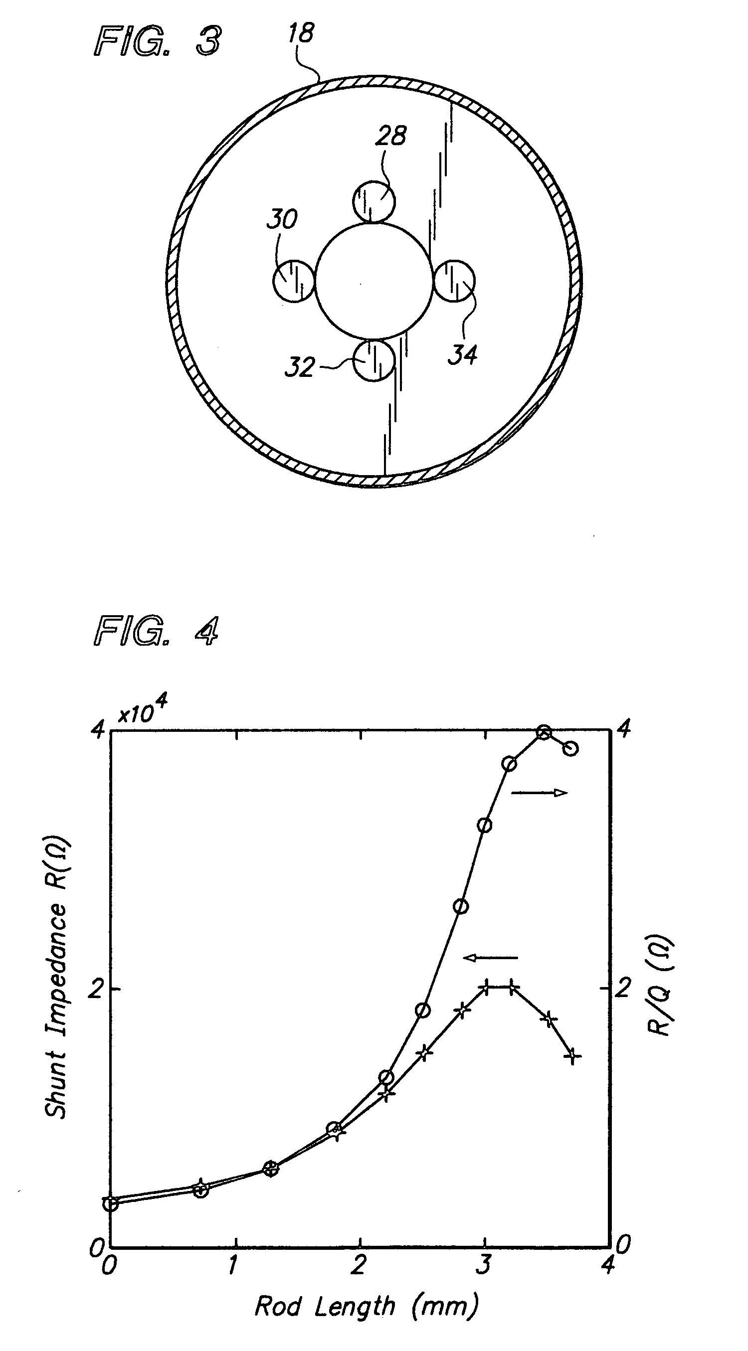
[0025] The rods effectively increase the shunt impedance of the cavity and thus increase the strength of a resonance signal emitted from the cavity upon passage of a

Problems solved by technology

A continuing challenge in the design and operation of particle accelerators is the determination of the precise characteristics of the particle beam at various points along the beam path.
Multi-cell structures are, however, more difficult to fabricate and tune.
However, improper cell-to-cell transverse alignment can couple power to all modes in the quadrupole band, with phase advance ranging from 0 to π.
This power must eventually be filtered out, which is more difficult in the case of small inter-mode spacing.
Howe

Method used


Image

  • Diagnostic resonant cavity for a charged particle accelerator
  • Diagnostic resonant cavity for a charged particle accelerator
  • Diagnostic resonant cavity for a charged particle accelerator

Examples


Embodiment Construction

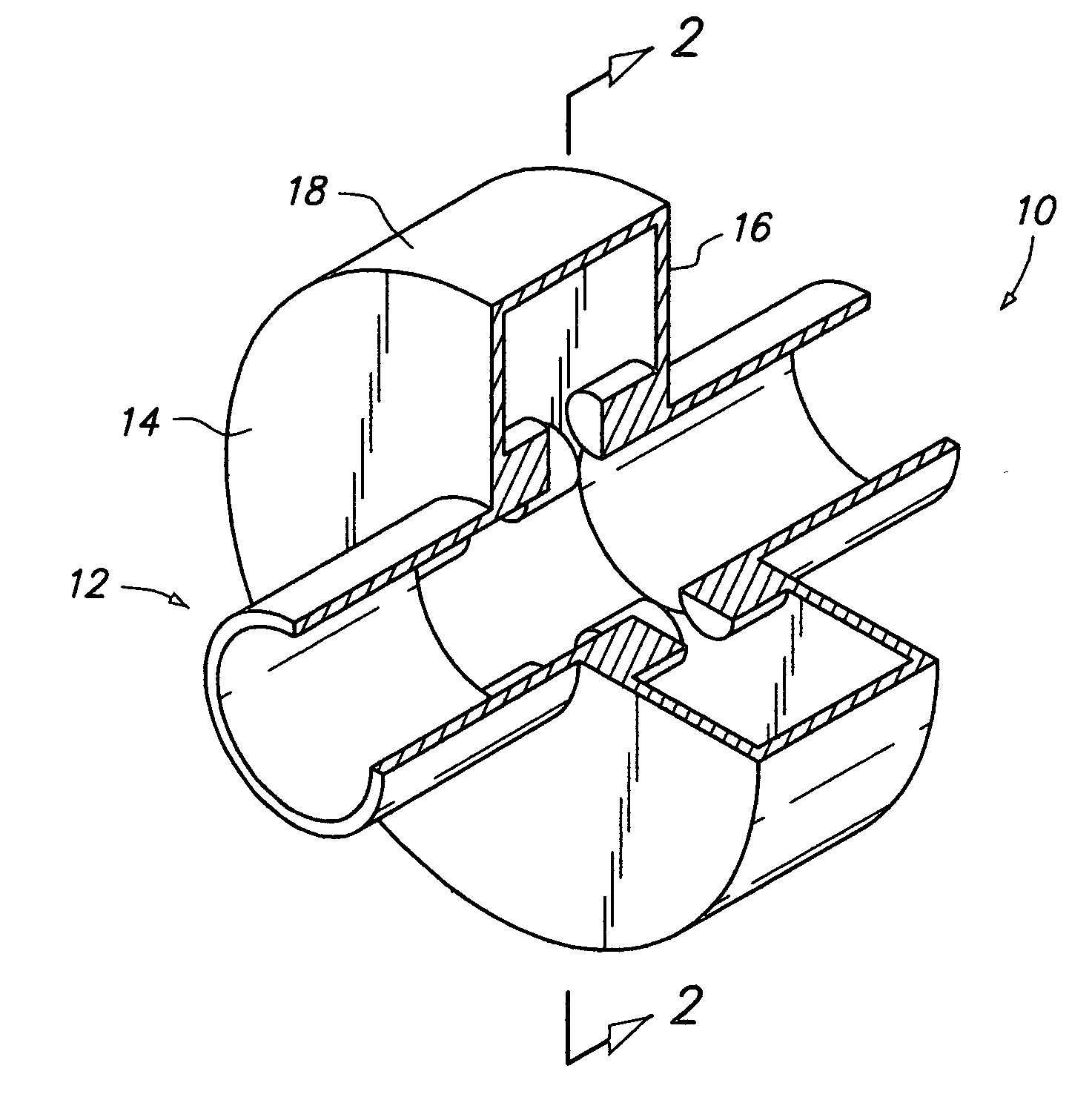
[0042] The term “resonant cavity” is used herein to mean a hollow electrically resonant structure that defines an interior volume through which a charged particle beam may be passed.

[0043] The electrons in high-energy research electron accelerators travel at nearly the speed of light and are bunched in time so that the bunch duration is only a small fraction of the period of one oscillation of the resonant cavities through which the electrons pass. The electron beam may be made up of many such bunches spaced at a regular time interval, or it may consist of a single bunch of electrons.

[0044] As noted above, the electric and magnetic fields within a resonant cavity oscillate at frequencies that are determined by the capacitance and inductance of the cavity. A resonant cavity typically has many harmonic resonances, or modes, each of which must be considered separately. A mode is characterized by the voltage it can impart to a charged particle traveling generally parallel to the beam ...


PUM


Abstract

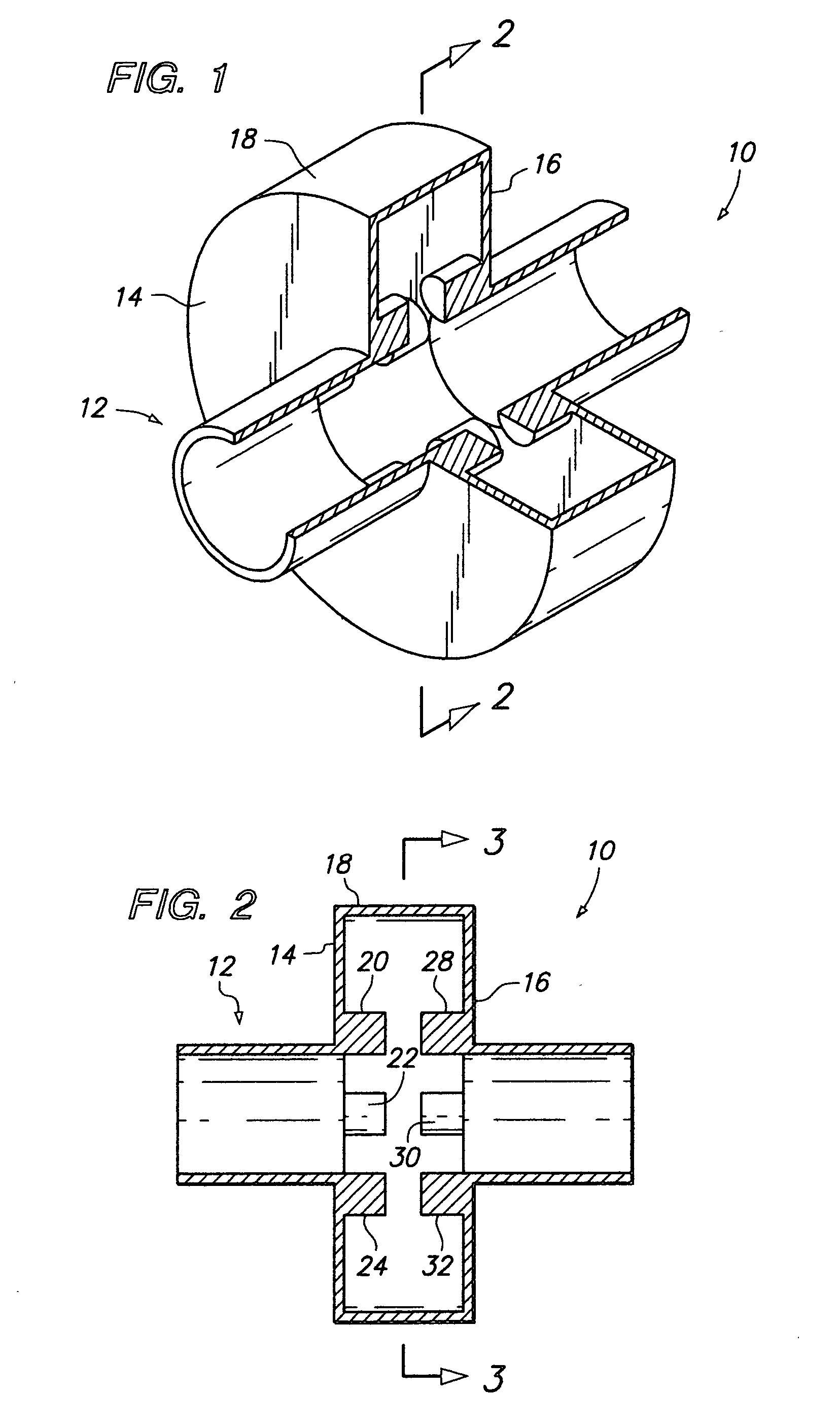
Disclosed is a diagnostic resonant cavity for determining characteristics of a charged particle beam, such as an electron beam, produced in a charged particle accelerator. The cavity is based on resonant quadrupole-mode and higher order cavities. Enhanced shunt impedance in such cavities is obtained by the incorporation of a set of four or more electrically conductive rods extending inwardly from either one or both of the end walls of the cavity, so as to form capacitive gaps near the outer radius of the beam tube. For typical diagnostic cavity applications, a five-fold increase in shunt impedance can be obtained. In alternative embodiments the cavity may include either four or more opposing pairs of rods which extend coaxially toward one another from the opposite end walls of the cavity and are spaced from one another to form capacitative gaps; or the cavity may include a single set of individual rods that extend from one end wall to a point adjacent the opposing end wall.

Description

FIELD OF THE INVENTION [0001] The present invention relates generally to electrically resonant cavities, and in particular to resonant cavities of the type used in electron beam and other charged particle accelerators. BACKGROUND OF THE INVENTION [0002] The invention described and claimed herein has application to accelerators used to produce charged particle beams, primarily electron beam accelerators. While the present invention is described herein primarily with reference to electron beam accelerators, the invention also has application to accelerators designed to produce beams of protons or other charged particles. [0003] All of the references cited herein are hereby incorporated by reference. [0004] In most charged particle accelerators there is a need to determine the size, position, cross-sectional shape, and other characteristics of the beam of charged particles produced by the accelerator, usually at various points along the path of the beam as it is accelerated along an ev...

Claims


Application Information

Patent Timeline
IPC IPC(8): H03B9/01
CPCH05H7/18H05H7/22
Inventor BAROV, NIKOLAI
Owner FARTECH
Why Eureka
Try Eureka