Welding system and consumable electrode welding method

Active Publication Date: 2007-05-31
PANASONIC CORP
View PDF6 Cites 9 Cited by
  • Summary
  • Abstract
  • Description
  • Claims
  • Application Information

AI Technical Summary

Benefits of technology

[0072] According to this process, in the weld starting time, by the unidirectional operation by which the actuator separates the torch, the velocity of the welding wire for the workpiece can be controlled. Therefore, vibration due to reversal of the torch velocity is not generated. Further, the velocity follow-up performance of the actuator which moves the welding torch is increased by means of the dedicated separation control system, whereby the response time and the acceleration and deceleration time can be reduced compared with those in the conventional process. Further, the control by the dedicated separation control system is not performed in u

Problems solved by technology

Therefore, the welding wire 101 can be excessively pressed against the base material

Method used


Image

  • Welding system and consumable electrode welding method
  • Welding system and consumable electrode welding method
  • Welding system and consumable electrode welding method

Examples


embodiment 1

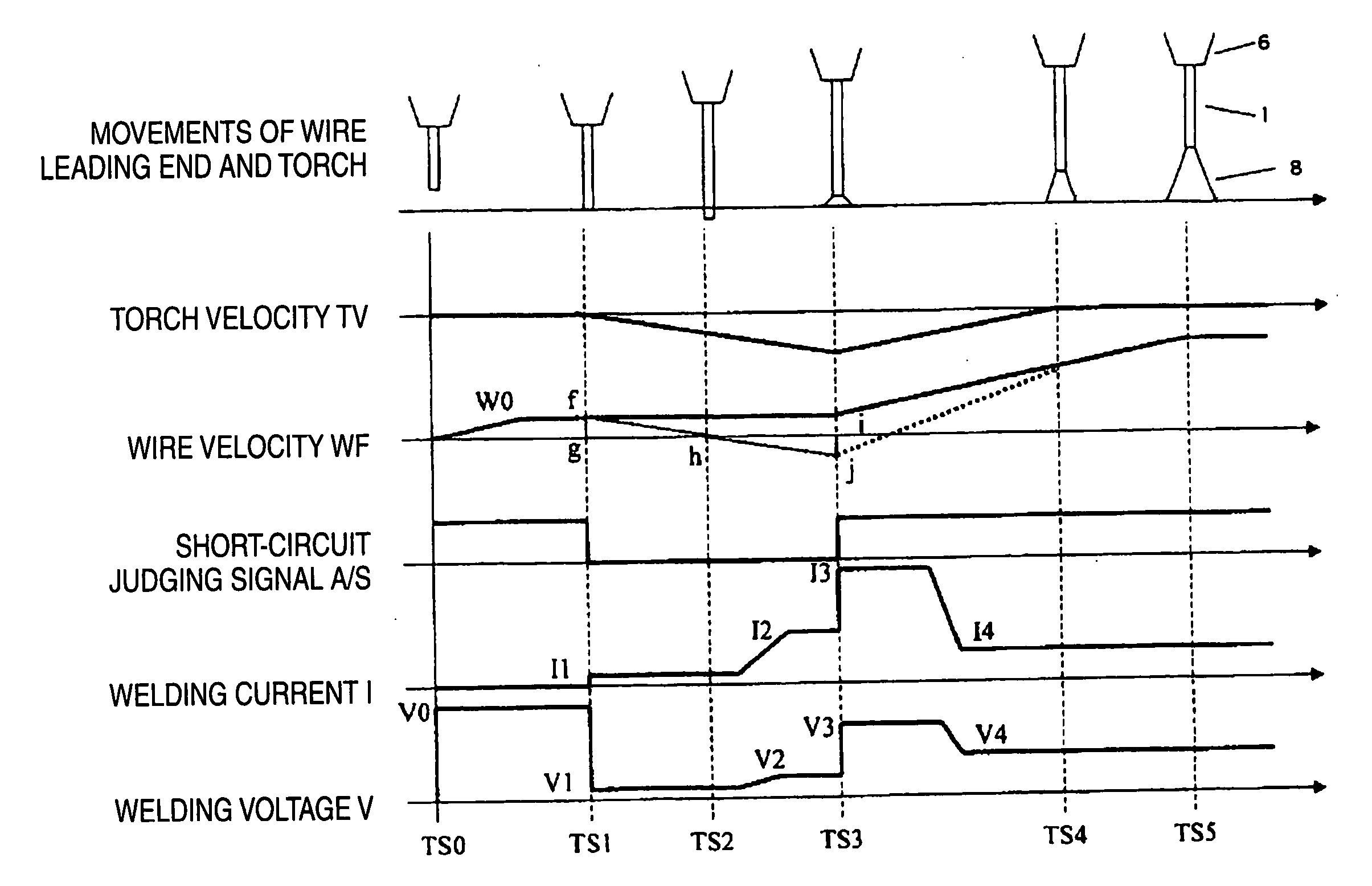
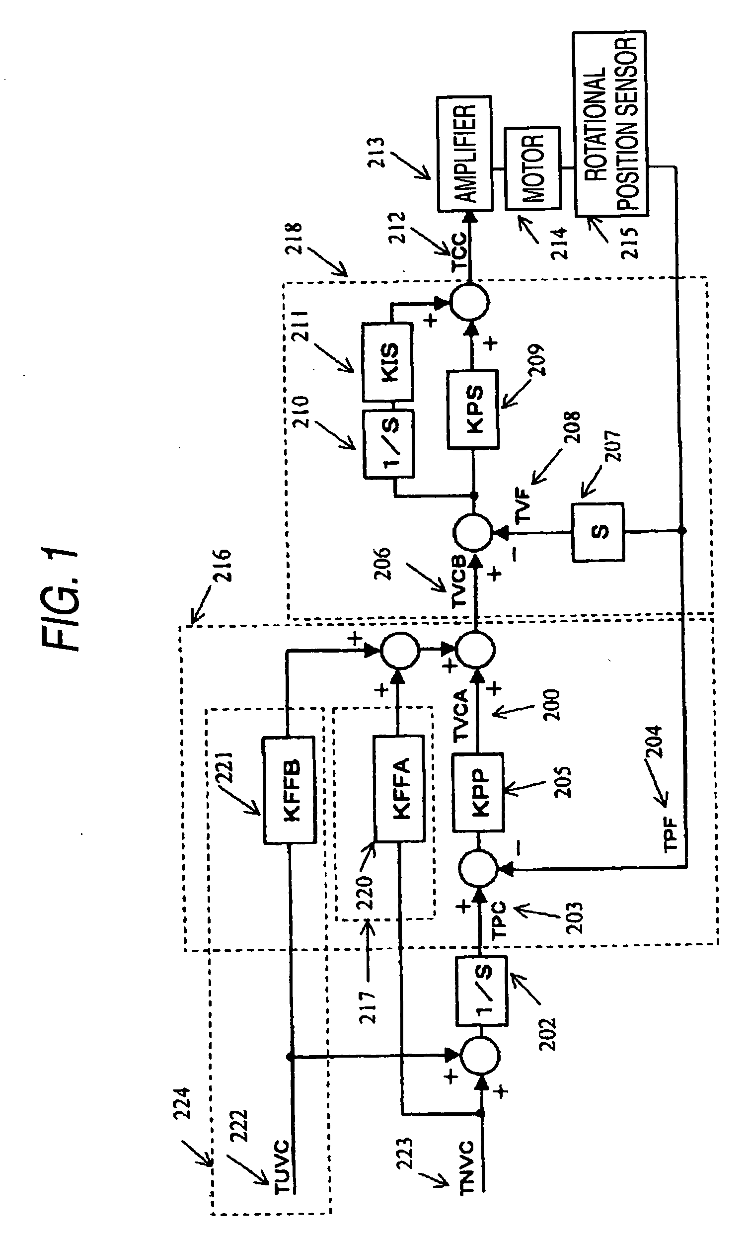
[0137] One embodiment of the invention will be described below with reference to FIGS. 1 to 3 and FIGS. 7 and 8.

[0138] Referring first to FIGS. 2 and 3, construction of a welding system in this embodiment and a process of arc start will be described. Referring next to FIGS. 1, 7 and 8, a position control loop of a robot controller 10 in the embodiment will be described.

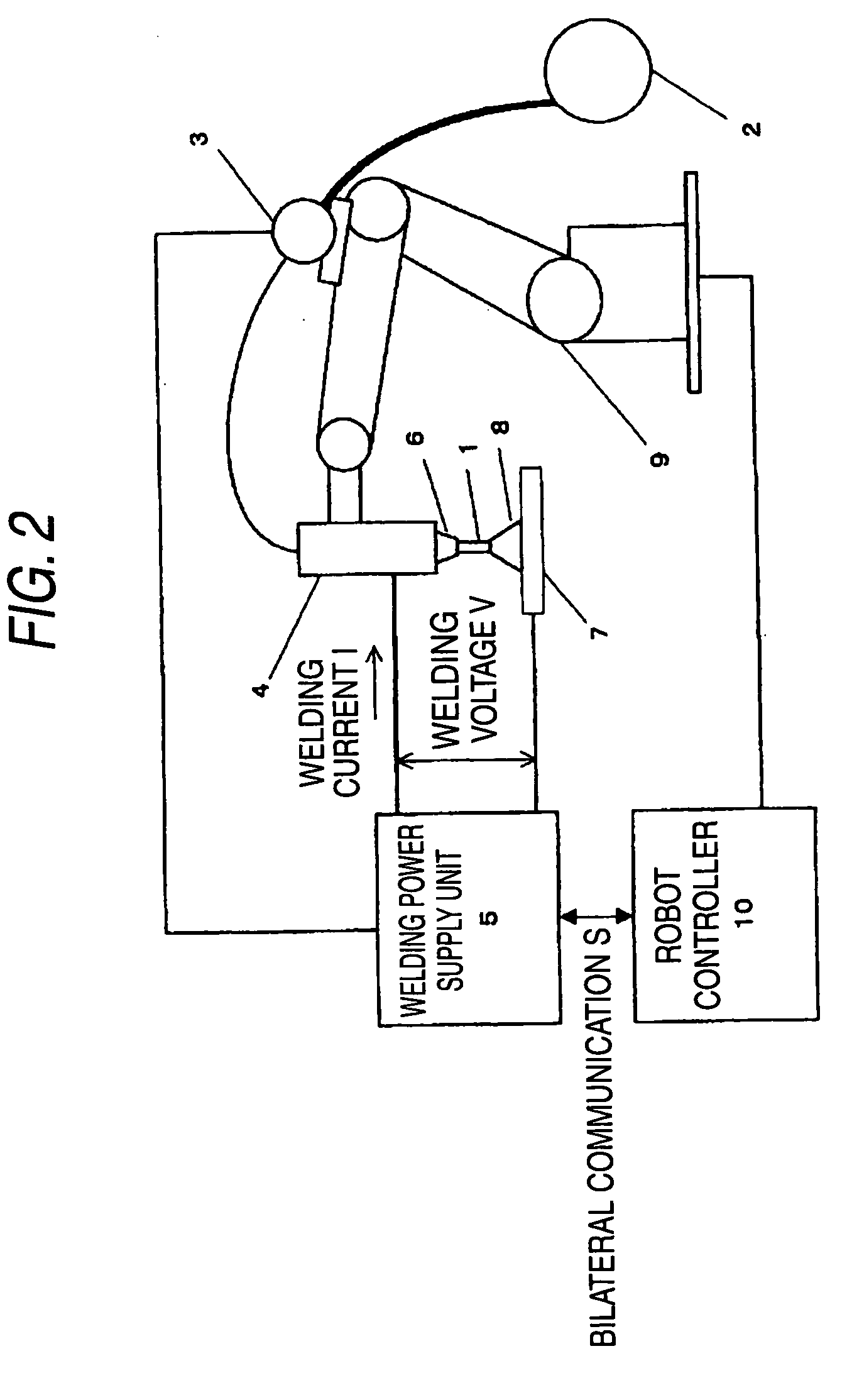
[0139]FIG. 2 is a constitutional diagram showing an outline of a welding system in the embodiment. A welding wire 1 that is a consumable electrode is supplied from a wire spool 2 in a direction of a welding torch 4 by a wire feeding motor 3.

[0140] A welding power supply unit 5 applies the predetermined welding current I and welding voltage V between the welding wire 1 and a base material 7 that is a workpiece through the welding torch 4 and a welding chip 6 thereby to generate an ark 8, and controls the wire feeding motor 3 to perform welding.

[0141] A robot manipulator 9, holding the welding torch 4, locates it in...


PUM

PropertyMeasurementUnit
Velocityaaaaaaaaaa
Threshold limitaaaaaaaaaa
Torqueaaaaaaaaaa

Abstract

A torch is moved by a manipulator in a direction separating from a base material 7 while a wire is supplied, whereby an actuator driving the robot manipulator can control a velocity of the wire for a workpiece by a unidirectional operation of separating the torch, and vibration due to reverse of torch velocity is not generated. Further, by using a dedicated separation control system, velocity follow-up performance of the actuator moving the torch can be heightened without increasing overshoot in the usual operation time, and the acceleration and deceleration time of the manipulator can be reduced.

Description

TECHNICAL FIELD [0001] The present invention relates to a control method of controlling a position of a welding robot driven by a motor BACKGROUND ART [0002] Recently, in the industry of welding, more effort into improvement of productivity is continued every day. Particularly, requests to reduce a short-time stop of a production line caused by minor troubles and to reduce a tact time become higher than before. [0003] Various factors are thought as causes of the stop of the production line. The largest cause is a trouble caused by poor arc start. [0004] Therefore, in the arc start in a conventional consumable electrode type welding process, when a start signal is input from the exterior part, a robot manipulator is driven to move a welding torch to a weld-start-position which has been previously taught. Thereafter, in a state where feeding of a wire is stopped, the welding torch is moved by the robot manipulator nearly in the feeding direction of the welding wire and a leading end o...

Claims


Application Information

Patent Timeline
IPC IPC(8): B23K9/10
CPCB23K9/0671B23K9/125B23K9/126
Inventor NAKATA, HIROYUKIMUKAI, YASUSHIIKEDA, TATSUYAMASUNAGA, NAOTOKOWA, MASARUHONUCHI, YASUYOSHI
Owner PANASONIC CORP
Why Eureka
Try Eureka