In addition to increased leakage if clearances are not maintained, such as during a high-G maneuver, there is the potential for increases in engine vibration.
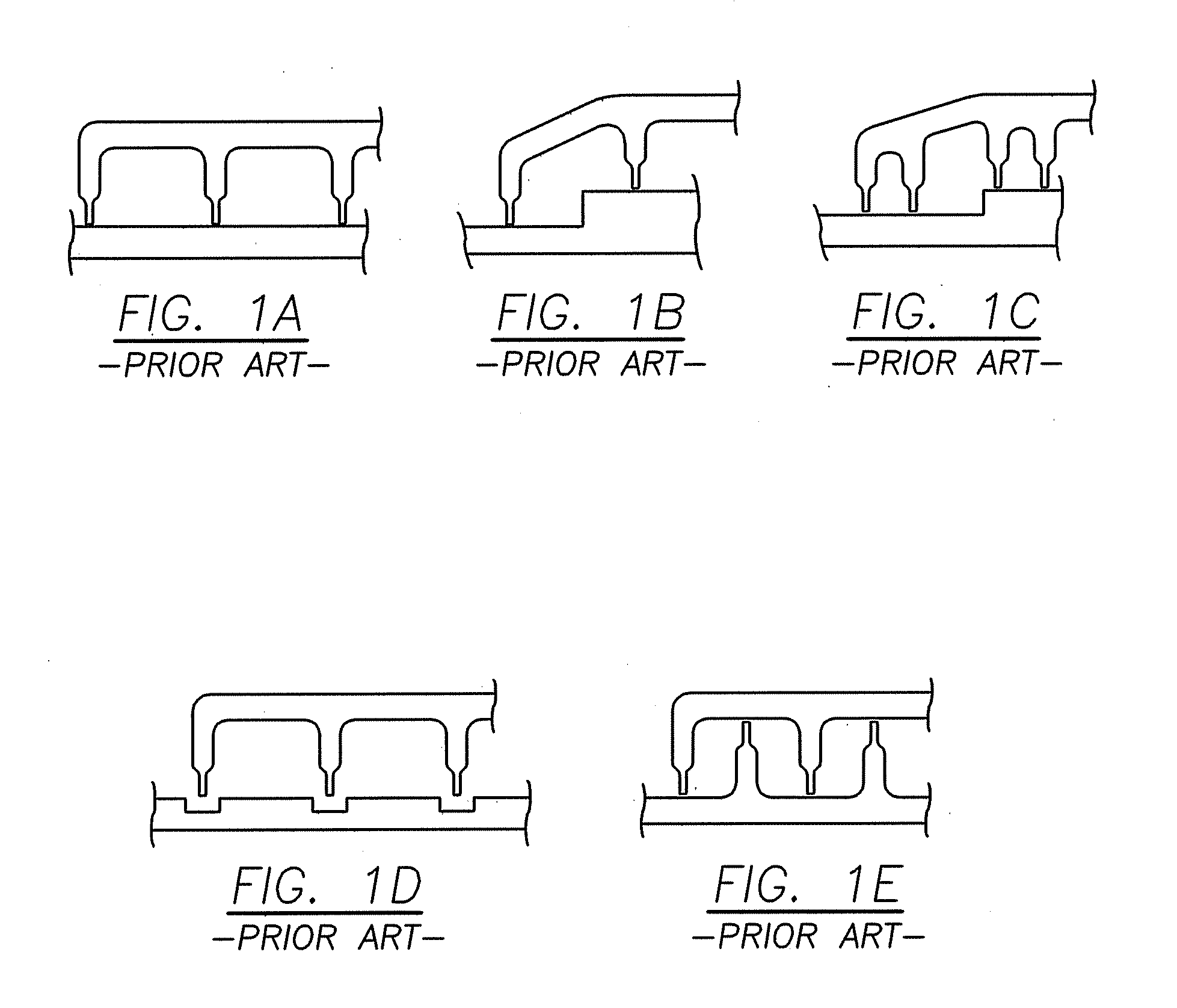
Straight-thru labyrinth seals (FIG. 1A) are the most sensitive to clearance changes, with large clearances resulting in a carryover effect.
Other problems associated with labyrinth seals arise from
heat generation due to knife edge to seal land rub, debris from hardcoated knife edges or seal lands being carried through engine passages, and excessive engine vibration.
When seal teeth rub against seal lands, it is possible to generate large amounts of heat.
This heat may result in reduced material strength and may even cause destruction of the seal if heat conducted to the rotor causes further interference.
Other difficulties with hardcoated knife edges include
low cycle fatigue life debits, rub induced tooth-edge
cracking, and the possibility of handling damage.
As mentioned previously, this vibration can be caused by improper maintenance of radial clearances.
However, it can also be affected by the spacing of
labyrinth seal teeth, which can produce
harmonics and result in high vibratory stresses.
However, with
current technology, all
brush seals will eventually wear to line on line contact at the point of greatest initial interference.
Although brush seal leakage generally decreases with
exposure to repeated pressure loading, incorporating brush seals where extreme pressure loading occurs may cause a “blow over” condition resulting in permanent deformation of the seal wires.
Brush seals have been used in sealing bearing compartments, however
coke on the wires may result in accelerated wear and their
leakage rate is higher than that of carbon seals.
One additional limitation of brush seals is that they are essentially unidirectional in operation, i.e., due to the angulation of the individual wires, such seals must be oriented in the direction of rotation of the moving element.
Rotation of the moving element or rotor in the opposite direction, against the angulation of the wires, can result in permanent damage and / or failure of the seal.
Although bristle wear may be reduced in this design, it is believed that the seal created at the interface of the sliding ring and rotor is unsatisfactory.
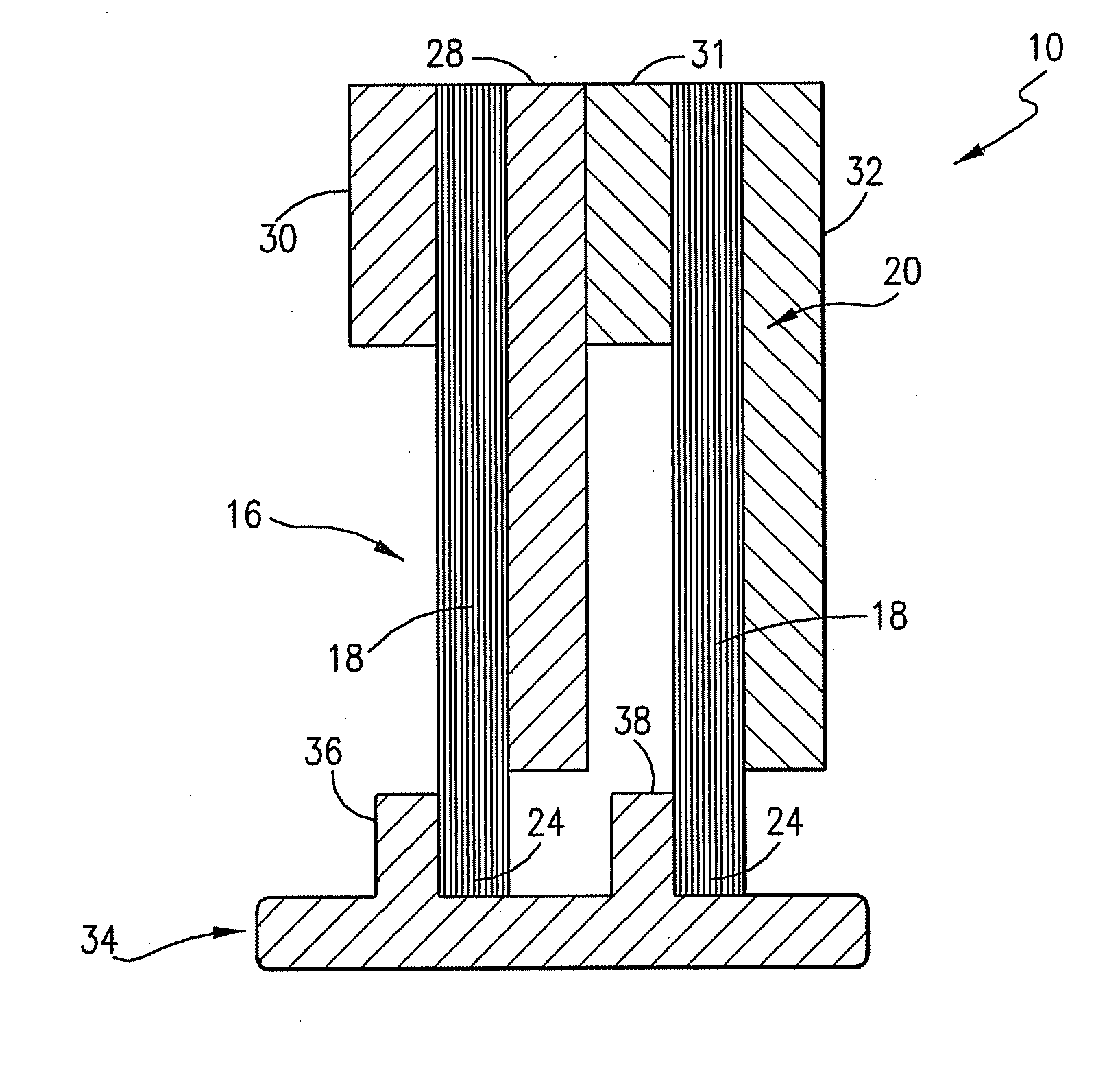
It has been found that one limitation of the design disclosed in the '009 patent is a potential problem with “roll over” under
pressure load, i.e. the shoes can tip or pivot in the axial direction thus creating a leakage path.
Their
low leakage rates in comparison to labyrinth or brush seals are well-suited to this application, however they are very sensitive to pressure balances and tolerance stack-ups.

