Pick and place machine with component placement inspection

a technology of component placement and pick and place machine, which is applied in the field can solve the problems of consuming plant floor space as well as programming time maintenance efforts, affecting the operation of pick and place machines, and reducing the possibility, so as to facilitate the provision of relatively high-power illumination.

Inactive Publication Date: 2007-05-31
CYBEROPTICS
View PDF99 Cites 31 Cited by
  • Summary
  • Abstract
  • Description
  • Claims
  • Application Information

AI Technical Summary

Benefits of technology

[0011] Embodiments of the present invention improve upon component level inspection performed by pick and place machines. Such improvements include stereovision imaging of the intended placement location; enhanced illumination to facilitate the provision of relatively high-power illumination in the restricted space near the placement nozzle(s); optics to allow image acquisition device to view the placement location from an angle relative to a plane of the placement location, thereby reducing the possibility of such images being obstructed by the component; techniques for rapidly acquiring images with commercially available CCD arrays such that acquisitions of before and after images do not substantially impact system throughput; and image processing techniques to provide component inspection and verification information. These and other advantages of embodiments of the present invention will be apparent from the description below.

Problems solved by technology

Pick and place machine operation is challenging.
While such systems provide highly useful inspection, they do consume plant floor-space as well as programming time maintenance efforts and the like.
While the disclosure of Asai et al. marks one attempt to employ in-machine component level inspection, there remains much work to be done.
Thus, optics intended to image a plurality of placement events also move in x and / or y. Accordingly, the size and mass (inertial load) of the optical system itself can be prohibitive of on-head use in gantry-style machines.
For pick and place machines having heads that move in x and / or y, increased mass is an issue because of the increased inertia.
Given a certain motive power provided by the electromechanical system of the pick and place machine, increased mass causes decreased acceleration.
Size, that is volume and / or shape of the optical system attached to the moving head, can also be a problem for a number of reasons.
Another reason that the size and / or shape of the head can become a problem is that there are generally a relatively large number of cables, tubes, motors, and other structures mounted to the head.
Adding something that may conflict with assembly or maintenance of the machine is generally disfavored.

Method used


Image

  • Pick and place machine with component placement inspection
  • Pick and place machine with component placement inspection
  • Pick and place machine with component placement inspection

Examples


Embodiment Construction

[0034] Although embodiments of the present invention will be described with respect to a gantry-style pick and place machine, those skilled in the art will recognize that embodiments of the present invention are applicable to other forms of pick and place machines.

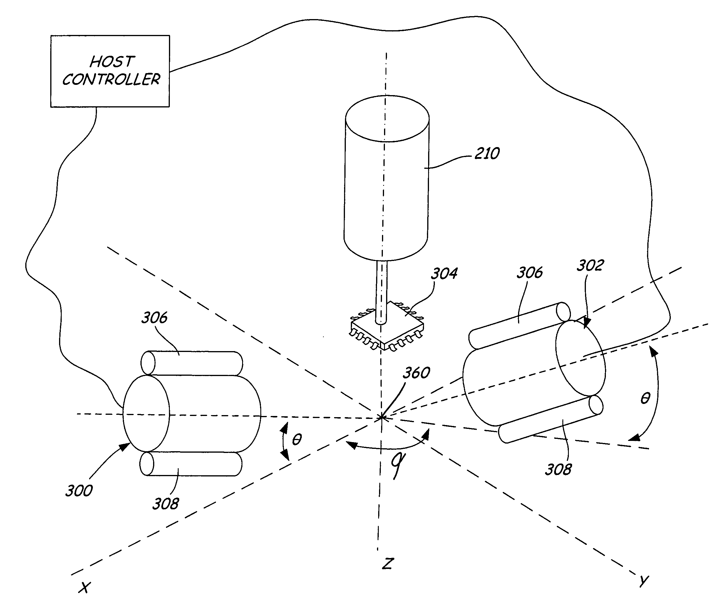
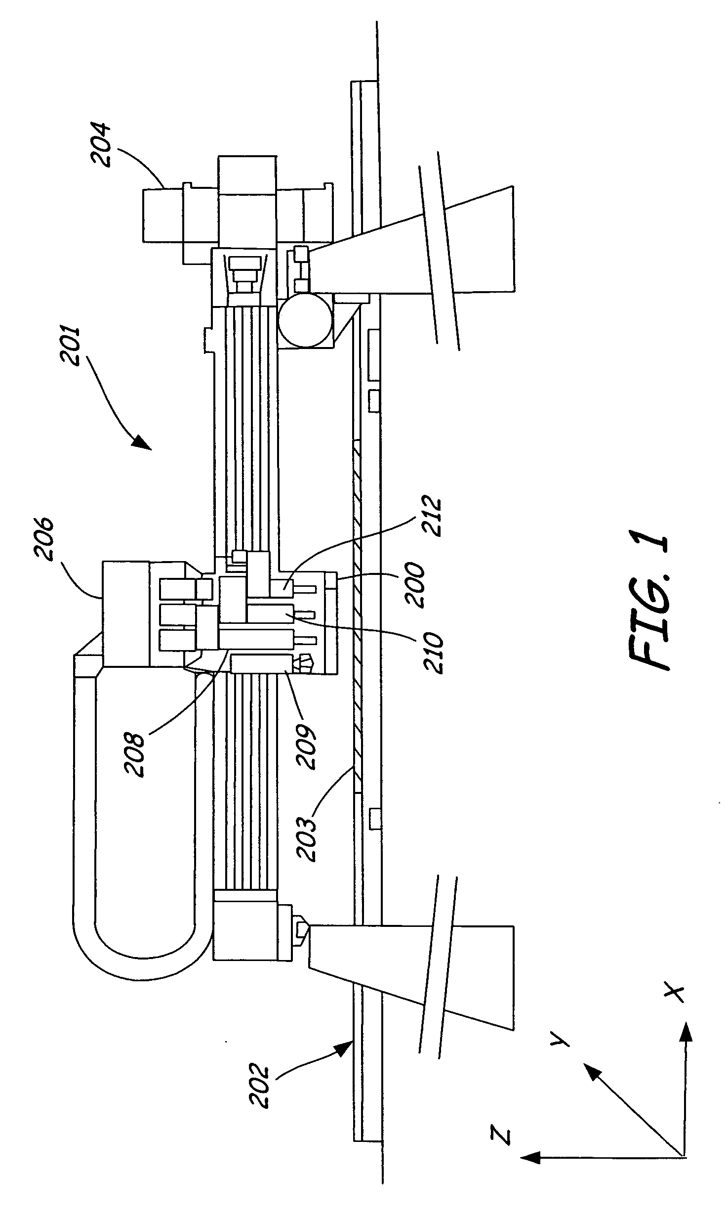
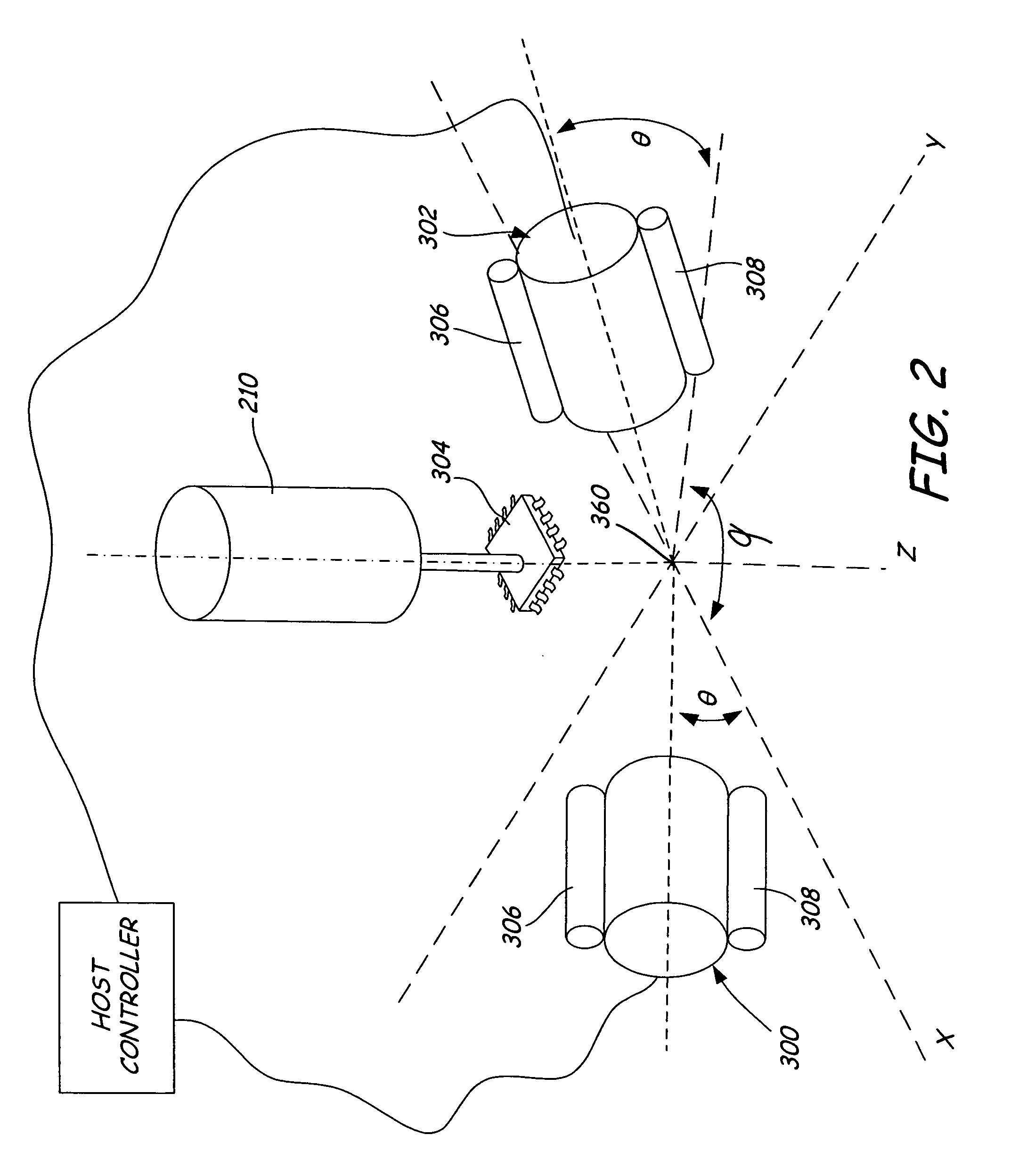
[0035]FIG. 1 is a diagrammatic view of an exemplary pick and place machine 201 with which embodiments of the present invention are applicable. Pick and place machine 201 receives a workpiece, such as circuit board 203, via transport system or conveyor 202. A placement head 206 then obtains one or more electrical components to be mounted upon workpiece 203 from component feeders (not shown) and moves in x, y and z directions to place the component in the proper orientation at the proper location upon workpiece 203. Placement head 206 may include a sensor 200 that may pass under components held by nozzles 208, 210, 212 as placement head 206 moves the component(s) from pickup locations to placement locations. Sensor 200 allo...


PUM

PropertyMeasurementUnit
diameteraaaaaaaaaa
time delayaaaaaaaaaa
photosensitiveaaaaaaaaaa

Abstract

Improved component placement inspection and verification is performed by a pick and place machine. Improvements include stereovision imaging of the intended placement location; enhanced illumination to facilitate the provision of relatively high-power illumination in the restricted space near the placement nozzle(s); optics to allow image acquisition device to view the placement location from an angle relative to a plane of the placement location, thereby reducing the possibility of such images being obstructed by the component; techniques for rapidly acquiring images with commercially available CCD arrays such that acquisition of before and after images does not substantially impact system throughput; and image processing techniques to provide component inspection and verification information.

Description

CROSS REFERENCE TO RELATED APPLICATIONS [0001] This application is a divisional application of U.S. patent application Ser. No. 10 / 291,074, filed Nov. 8, 2002, which application claims priority to the following prior provisional applications: Ser. No. 60 / 338,233 filed Nov. 13, 2001 entitled INSPECTION METHODS FOR A PICK AND PLACE MACHINE; Ser. No. 60 / 356,801 filed Feb. 13, 2002 entitled PICK AND PLACE MACHINE WITH COMPONENT PLACEMENT INSPECTION; and Ser. No. 60 / 374,964 filed Apr. 22, 2002 entitled IMPROVED INSPECTION. Each and every provisional application listed above is incorporated by reference herein in its entirety.COPYRIGHT RESERVATION [0002] A portion of the disclosure of this patent document contains material which is subject to copyright protection. The copyright owner has no objection to the facsimile reproduction by anyone of the patent document or the patent disclosure, as it appears in the Patent and Trademark Office patent files or records, but otherwise reserves all c...

Claims


Application Information

Patent Timeline
Patent Type & Authority Applications(United States)
IPC IPC(8): H04N7/18G06K9/00H04N13/00H05K13/04H05K13/08
CPCH04N13/0059H04N13/0207H04N13/0217H04N13/0239H04N13/0253Y10T29/53191H05K13/0413H05K13/08Y10T29/53087Y10T29/49778H04N2013/0081H04N13/194H04N13/254H04N13/207H04N13/218H04N13/239H05K13/0812H05K13/0818
Inventor DUQUETTE, DAVID W.HAUGEN, PAUL R.FISHBAINE, DAVIDGAIDA, JOHN D.MADSEN, DAVID D.DALE, THEODORE PAULLIBERTY, TODD D.BUCHIKA, BRANT O.ROTH, SCOTT D.BUSHMAN, THOMAS W.
Owner CYBEROPTICS
Why Eureka
Try Eureka