
Characterizing Broadband Communication Networks

a broadband communication network and network technology, applied in the field of characterization of broadband communication networks, can solve the problems of limited data storage amount, network damage or other detrimental phenomena, and few customers cannot receive one or more channels clearly

Active Publication Date: 2007-05-31
VIAVI SOLUTIONS INC
View PDF6 Cites 47 Cited by
  • Summary
  • Abstract
  • Description
  • Claims
  • Application Information

AI Technical Summary

Problems solved by technology

The proper operation of cable systems involves field testing, because the cable plant is dispersed throughout the entire cable service area, the network can experience damage or other detrimental phenomena in varied, isolated portions of the network.
As a result, many customers may have excellent service, while a few customers cannot receive one or more channels clearly due to a localized problem.
However, there is a limit to the amount of data that may be stored, and the information that a technician may find useful is not always predictable.

Method used


Image

  • Characterizing Broadband Communication Networks
  • Characterizing Broadband Communication Networks
  • Characterizing Broadband Communication Networks

Examples


Embodiment Construction

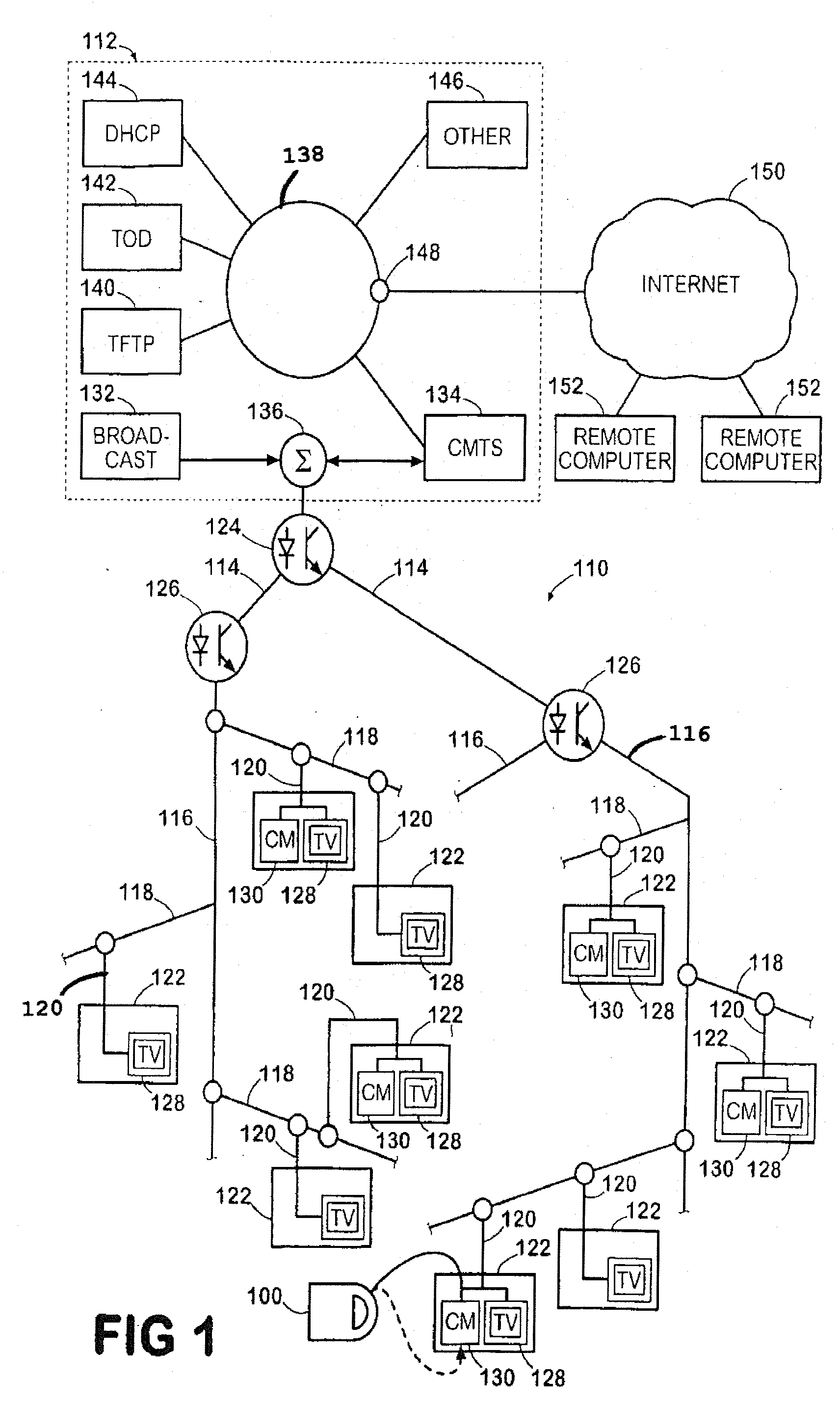
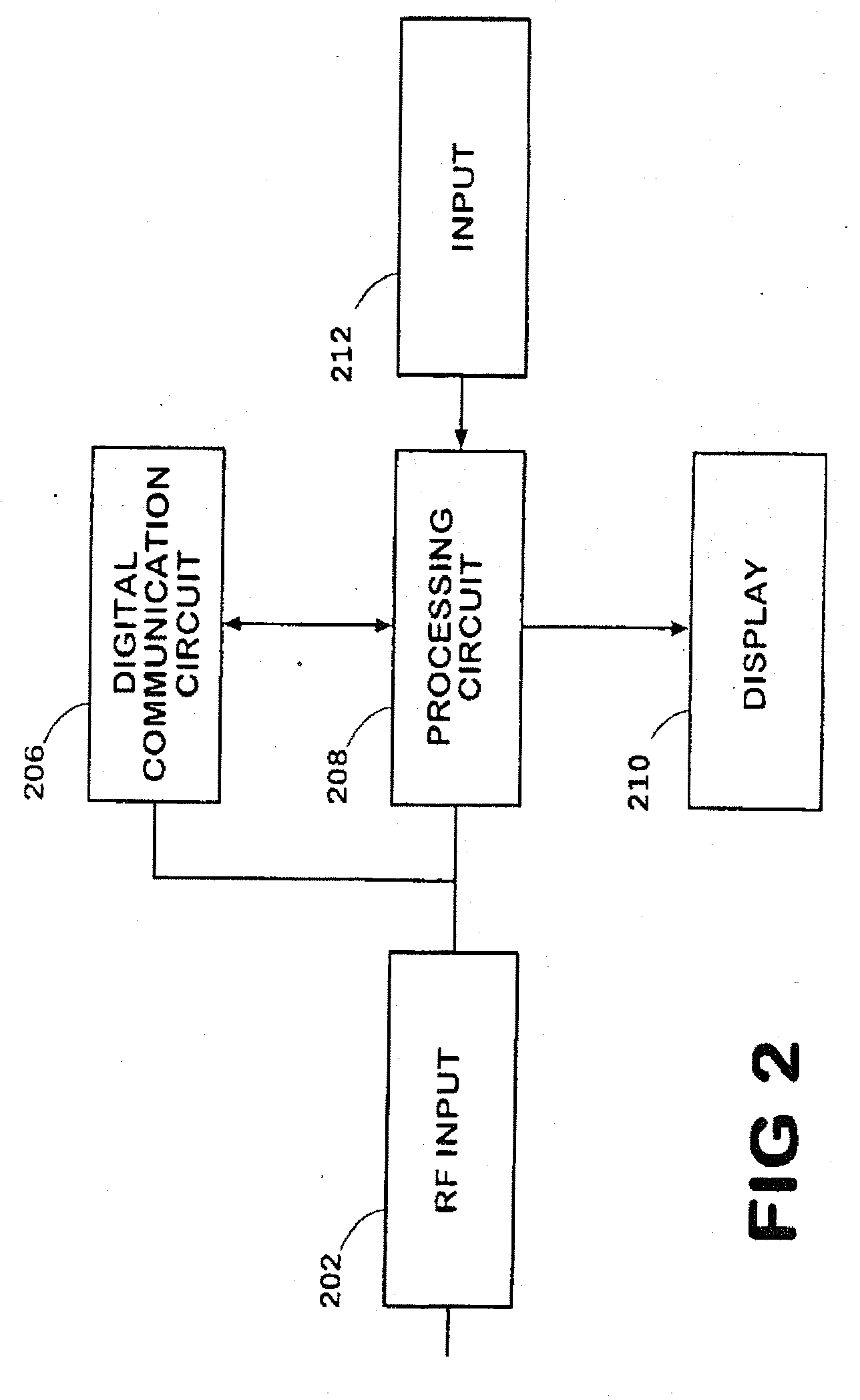
[0028] An exemplary test configuration, illustrated in FIG. 1, employs an analysis device 100, according to the present invention, within a communication network 110, which is a land-based broadband network typically known as a cable network. In the embodiment described herein, the communication network 110 is a hybrid fiber coax (HFC) network, which employs both fiber optic links and coaxial cable to effect radio frequency communications between a plurality of subscribers and a network headend 112. The network headend 112 is further operable to provide Internet communications between a plurality of subscribers and one or more remote computer devices 152 connected to the Internet 150. The computer devices 152 are external to the communication network 110. The analysis device 100 is operable to test multiple parameters of the network, including by way of example, the signal strength at a remote location of the network 110, whether Internet connectivity is available at remote location...


PUM


Abstract

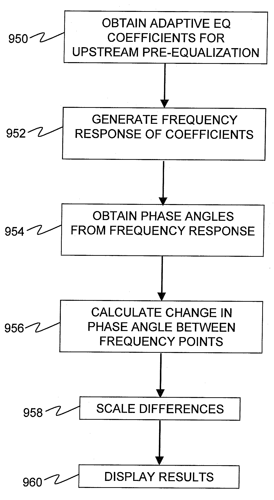
A remote testing device, including a cable modem circuit, requests an IP address from a remote cable modem termination system (CMTS) and receives back IP connection information including adaptive equalizer coefficients, which represent compensation and / or correction for transmission path noise. Using the equalizer coefficients, the remote testing device can determine a phase response, phase angles for each frequency increment over a channel bandwidth, and group delay.

Description

CROSS-REFERENCE TO RELATED APPLICATIONS [0001] The present invention claims priority from U.S. Patent Application No. 60 / 735,648 filed Nov. 10, 2005, which is incorporated herein by reference.TECHNICAL FIELD [0002] The present invention relates to the characterization of broadband communication networks, and in particular to generating phase response and / or group delay information of a transmission path in a broadband communication network. BACKGROUND OF THE INVENTION [0003] Cable networks are communication networks that communicate broadband communication signals between a centralized headend and a plurality of customer premise devices. Cable networks have many forms, but typically include a dispersed network of coaxial cable. Many cable networks, known as hybrid fiber coax or HFC networks, further include a substantial portion of fiber optic lines. [0004] Historically, cable networks were employed primarily for the delivery of the television program signals. To this end, the cable...

Claims


Application Information

Patent Timeline
IPC IPC(8): H04L5/16
CPCH04L1/24H04L25/0216H04L25/03343H04L2025/03808
Inventor OKAMOTO, KOJI
Owner VIAVI SOLUTIONS INC
Learn More