Transmission apparatus and peak suppression method

a technology of transmission apparatus and peak suppression method, which is applied in the direction of electrical apparatus, digital transmission, secret communication, etc., can solve the problems of increasing the size of the amplifier, increasing power consumption, and expensive amplifiers, and achieve the effect of improving the overall throughput of the system

Inactive Publication Date: 2007-05-31
PANASONIC CORP
View PDF10 Cites 23 Cited by
  • Summary
  • Abstract
  • Description
  • Claims
  • Application Information

AI Technical Summary

Benefits of technology

[0010] According to the present invention, it is possible to improve overall throughput of a system through peak suppression by suppressing peaks using some frequencies in a communication band.

Problems solved by technology

When the peak voltage of a signal increases in transmission due to the overlap of the phases of in this way, an amplifier with a dynamic range including peak electric power is required to amplify the transmission signal, which increases the size of the amplifier and also increases power consumption.
Furthermore, an increase in peak power of a signal during transmission requires an amplifier capable of keeping linearity over an extensive area, hence an expensive amplifier.

Method used


Image

  • Transmission apparatus and peak suppression method
  • Transmission apparatus and peak suppression method
  • Transmission apparatus and peak suppression method

Examples


embodiment 1

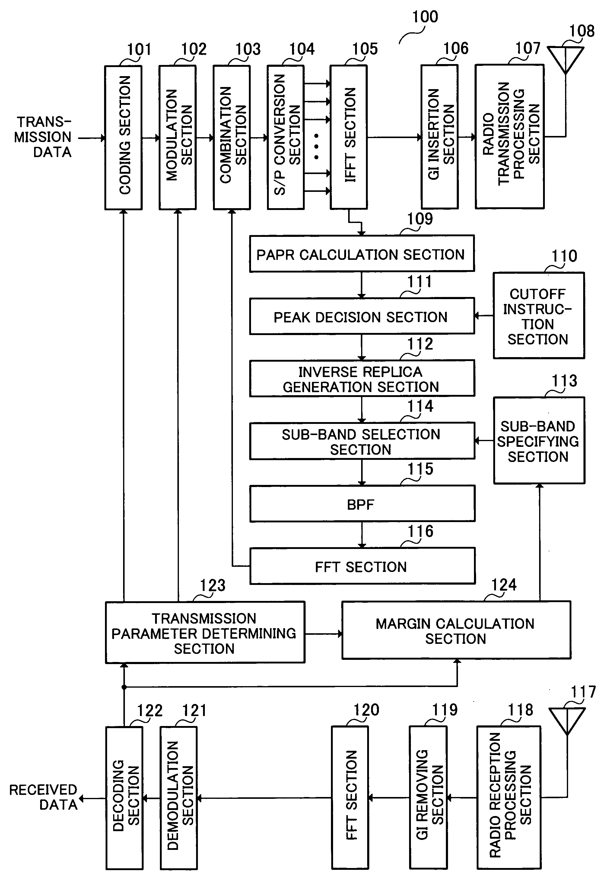
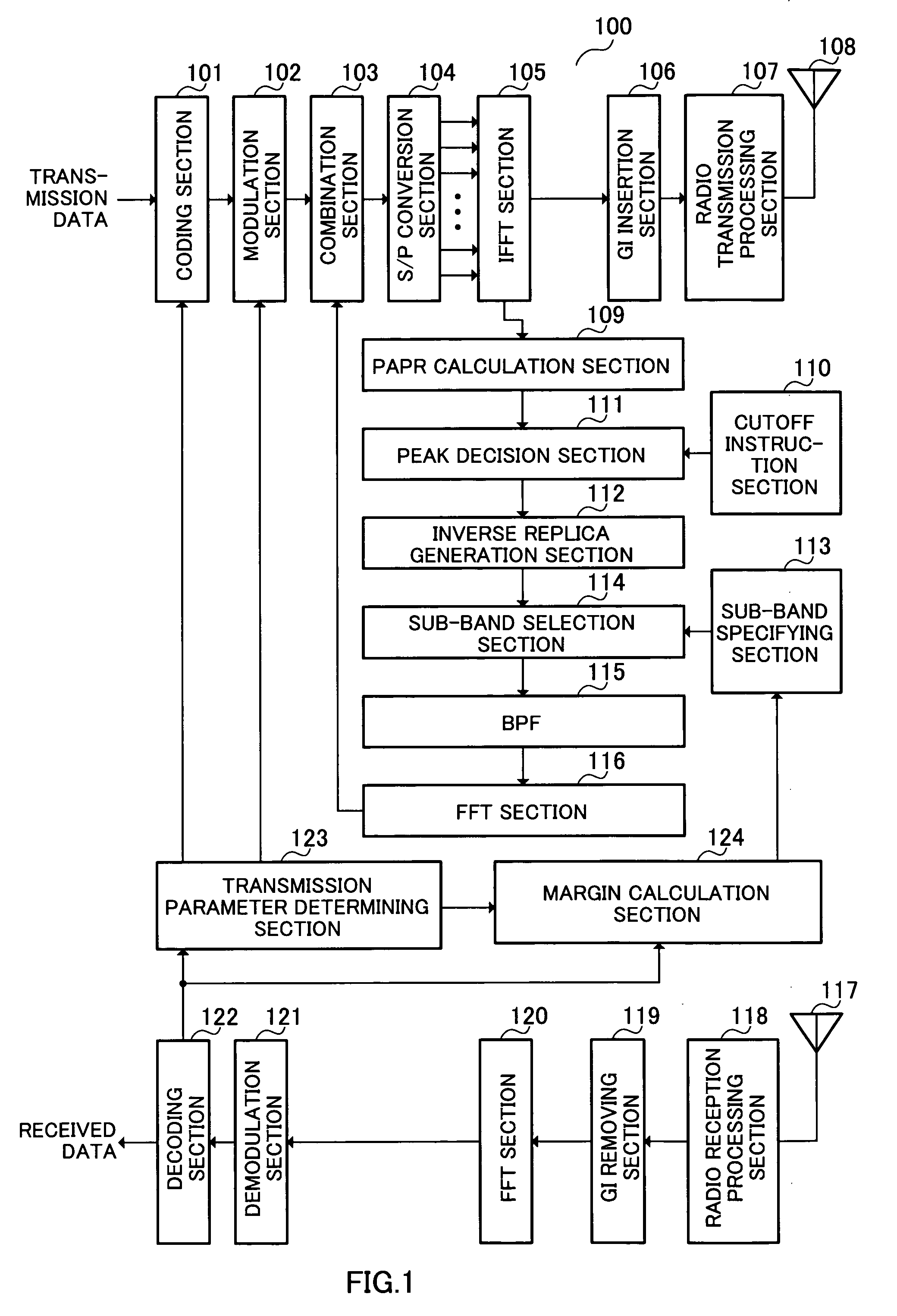
[0034]FIG. 1 is a block diagram showing the configuration of radio communication apparatus 100 according to Embodiment 1 of the present invention.

[0035] Coding section 101 codes transmission data at a coding rate from coding rate information input from transmission parameter determining section 123 and outputs the coded transmission data to modulation section 102.

[0036] Modulation section 102 modulates transmission data input from coding section 101 according to a modulation scheme based on modulation scheme information input from transmission parameter determining section 123 and outputs the modulated transmission data to combination section 103.

[0037] Based on inverse replica information, which is information about the waveform with an inverse characteristic of the waveform equal to or higher than a threshold input from FFT section 116 (hereinafter “inverse replica”), combination section 103 combines the waveform of the transmission data input from modulation section102 and the...

embodiment 2

[0071]FIG. 14 is a flowchart showing operation of a wireless communication apparatus when suppressing peaks. The radio communication apparatus according to this embodiment 2 has the same configuration as that in FIG. 1, and therefore explanations thereof will be omitted.

[0072] Peak suppression operation by the radio communication apparatus will be explained using FIG. 14 and FIG. 15.

[0073] First, IFFT section 105 performs IFFT on transmission data (step ST1401).

[0074] Next, PAPR calculation section 109 measures PAPR (step ST1402).

[0075] Next, as shown in FIG. 4, peak decision section 111 decides whether or not there is a peak whose PAPR is equal to or higher than threshold (a) from threshold information input from cutoff instruction section 110 (step ST1403).

[0076] When there is a peak whose PAPR is equal to or higher than threshold α, sub-band selection section 114 sets K=0 (step ST1404).

[0077] Next, sub-band selection section 114 selects N (N: natural number, equal to or sma...

embodiment 3

[0086]FIG. 18 and FIG. 19 are flow charts showing peak suppression operation by a radio communication apparatus. The radio communication apparatus according to this embodiment 3 has the configuration similar to that in FIG. 1, and therefore explanations thereof will be omitted.

[0087] Peak suppression operation by the radio communication apparatus will be explained using FIG. 18 and FIG. 19.

[0088] First, IFFT section 105 performs IFFT on transmission data (step ST1801).

[0089] Next, PAPR calculation section 109 measures PAPR (step ST1802).

[0090] Next, peak decision section 111 decides whether or not there is a peak whose PAPR is equal to or higher than threshold (a) from threshold information input from cutoff instruction section 110 as shown in FIG. 4 (step ST1803).

[0091] When PAPR is equal to or higher than threshold α, FFT section 116 performs FFT on an inverse replica (step ST1804).

[0092] Next, combination section 103 combines the transmission signal and the inverse replica ...


PUM


Abstract

A transmission apparatus capable of improving overall throughput of a system by suppressing peaks using some frequencies in a communication band. In this apparatus, modulation section (102) adaptively modulates transmission data. Combination section (103) combines the waveform of the transmission data and the waveform of an inverse replica and suppresses peaks equal to or higher than a threshold. When there are peaks equal to or higher than a threshold, inverse replica generation section (112) extracts the waveform of a peak equal to or higher than the threshold and generates an inverse replica which is the waveform having the inverse characteristic of the extracted waveform. Where MCS is set for each subcarrier, sub-band selection section (114) selects the frequency of a subcarrier having large margin in reception quality and outputs the inverse replica within the range of the selected frequency to combination section (103).

Description

TECHNICAL FIELD [0001] The present invention relates to a transmission apparatus and a peak suppression method, and more specifically, to a transmission apparatus and a peak suppression method where transmission signals are transmitted by an OFDM scheme. BACKGROUND ART [0002] Conventionally, a multicarrier communication apparatus employing an OFDM scheme is resistant to multipath and fading and realizes high quality communication, and therefore multicarrier communication apparatuses employing the OFDM scheme are attracting attention as the apparatus capable of realizing high-speed radio transmission. In OFDM scheme communication, transmission data is converted to parallel data and transmitted by being superimposed on a plurality of subcarriers, and therefore there is no correlation between subcarriers. For this reason, when the phases of subcarriers overlap one another, OFDM symbols have extremely large signal amplitudes. When the peak voltage of a signal increases in transmission d...

Claims


Application Information

Patent Timeline
Patent Type & Authority Applications(United States)
IPC IPC(8): H04K1/10H04B1/707H04L27/26
CPCH04B1/707H04B2201/70706H04B2201/70707H04L27/2624
Inventor YOSHII, ISAMUMIYOSHI, KENICHICHENG, JUNNISHIO, AKIHIKOFUKUOKA, MASARU
Owner PANASONIC CORP
Why Eureka
Try Eureka