Techniques for positioning therapy delivery elements within a spinal cord or brain

a technology for spinal cords and brains, applied in the field of electric stimulation techniques, can solve the problems of increasing the amount of time and effort required to focus the stimulation on the desired body region, changing the required paresthesia pattern, and electrical energy may stimulate undesired portions of the brain or spinal cord

Inactive Publication Date: 2007-05-31
MEDTRONIC INC
View PDF6 Cites 75 Cited by
  • Summary
  • Abstract
  • Description
  • Claims
  • Application Information

AI Technical Summary

Problems solved by technology

It requires much time and effort to focus the stimulation on the desired body region during surgery.
The major practical problem with these systems is that even if the paresthesia (sensation of stimulation) location covers the pain area perfectly during surgery, the required paresthesia pattern often changes later due to lead migration, histological changes (such as the growth of connective tissue around the stimulation electrode), neural plasticity or disease progression.
As a result, the electrical energy may stimulate undesired portions of the brain or spinal cord.
Presently known systems are susceptible to lead migration.
Additionally, for some treatment applications, the lead just cannot be placed optimally to provide the desired treatment therapy.
With currently available systems, this often fails mostly due to the great thickness of the cerebral spinal fluid (CSF) layer.
With present single channel approaches, however, it is difficult to redirect paresthesia afterwards, even though limited readjustments can be made by selecting a different contact combination, pulse rate, pulse width or voltage.
Similar problems and limitations are present in drug infusion systems.
These systems, however, are limiting in that the steerable electric field is limited by the location of the electrodes.
If the electrodes move outside of the desired treatment area or if the desired stimulation area is different due to histological changes or disease migration, the desired treatment area may not be reached even by these steerable electrodes.
Further, even if these steerable electrodes may be able to stimulate the desired neural tissue, the distance from the electrodes to the tissue may be too large such that it would require greater electrical power to provide the desired therapy.
This not only more rapidly depletes the energy reserve, but it also may stimulate undesired neural tissue areas thereby creating undesired side effects such as pain, motor affects or discomfort to the patient.

Method used


Image

  • Techniques for positioning therapy delivery elements within a spinal cord or brain
  • Techniques for positioning therapy delivery elements within a spinal cord or brain
  • Techniques for positioning therapy delivery elements within a spinal cord or brain

Examples


Embodiment Construction

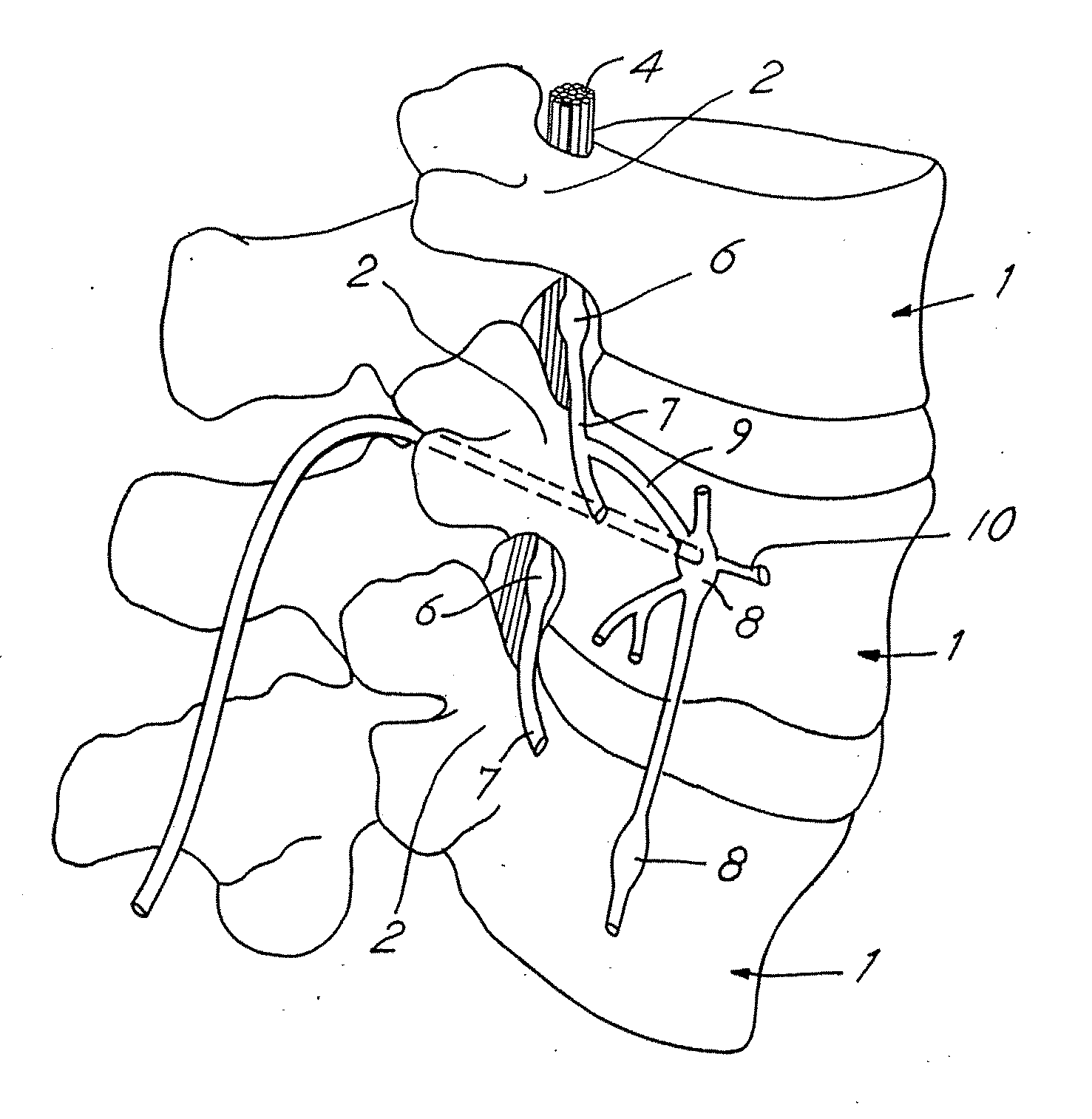
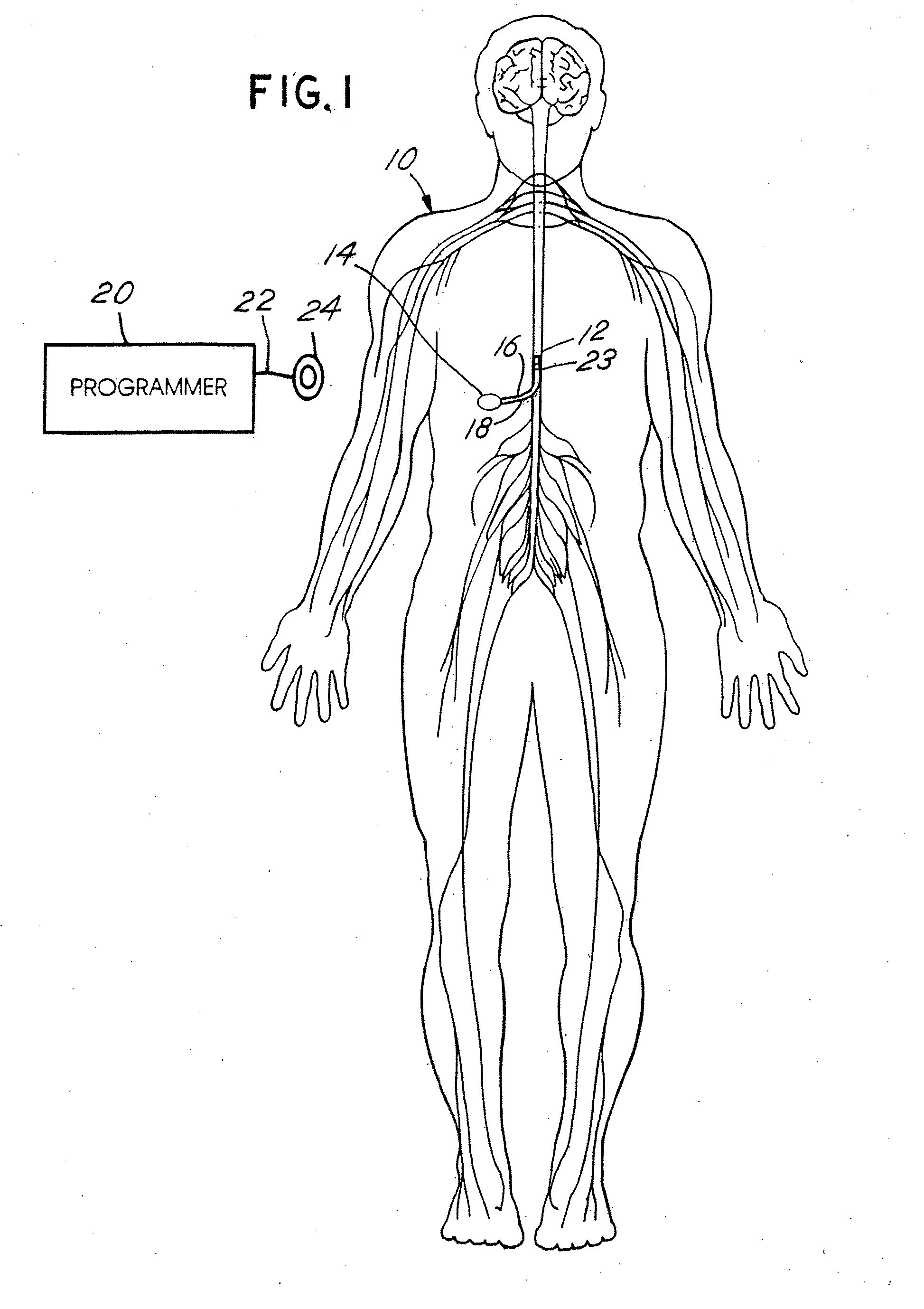
[0050]FIG. 1 depicts a neurostimulation therapy delivery device 14 in accordance with an embodiment of the present invention. Therapy delivery device 14 made in accordance with the preferred embodiment is preferably implanted below the skin of a patient or, alternatively, may be an external device. Therapy delivery device 14 may be implanted as shown in FIG. 1, in the abdomen or any other portion of the body 10. One or more leads 23 are positioned to stimulate a specific site in a spinal cord 12. Therapy delivery device 14 may take the form of a modified signal generator Model 7424 manufactured by Medtronic, Inc. under the trademark Itrel II which is incorporated by reference in its entirety. Lead 23 may take the form of any of the leads sold with the Model 7424, for stimulating a spinal cord, and is coupled to therapy delivery device 14 by one or more conventional conductors 16 and 18. Lead 23 may include a paddle lead, a lead having one or more therapy delivery devices such as sti...


PUM


Abstract

Apparatus and techniques to address problems associated with lead migration, patient movement or position, histological changes, neural plasticity or disease progression. Disclosed are techniques for implanting a lead having therapy delivery elements, such as electrodes or drug delivery ports, within a vertebral or cranial bone so as to maintain these elements in a fixed position relative to a desired treatment site. The therapy delivery elements may thereafter be adjusted in situ with a position control mechanism and / or a position controller to improve the desired treatment, such as electrical stimulation and / or drug infusion to a precise target. The therapy delivery elements may be positioned laterally in any direction relative to the targeted treatment site or toward or away from the targeted treatment site. A control system maybe provided for open- or closed-loop feedback control of the position of the therapy delivery elements as well as other aspects of the treatment therapy.

Description

RELATED APPLICATION [0001] This is a continuation application of U.S. Ser. No. 10 / 881,239 filed Jun. 30, 2004, which is a continuation application of U.S. Ser. No. 09 / 934,001 filed Aug. 21, 2001, now U.S. Pat. No. 6,795,737 issued Sep. 21, 2004, which is a division of U.S. Ser. No. 09 / 303,145 filed Apr. 30, 1999, now U.S. Pat. No. 6,319,241 issued Nov. 20, 2001, which is a continuation-in-part of the earlier filed co-pending patent application Ser. No. 09 / 070,136 entitled “Apparatus and Method for Expanding a Stimulation Lead Body in Situ,” filed on Apr. 30, 1998, now U.S. Pat. No. 6,161,047 issued Dec. 12, 2000, for which priority is claimed. The above-identified applications are incorporated herein by reference in their entireties, and priority to the above-identified applications is claimed.BACKGROUND OF THE INVENTION [0002] The present invention relates to stimulation or drug delivery systems, and more particularly relates to techniques for positioning the treatment therapy elem...

Claims


Application Information

Patent Timeline
Patent Type & Authority Applications(United States)
IPC IPC(8): A61N1/36A61M5/142A61M5/172A61N1/05A61N1/34
CPCA61M5/14276A61M5/1723A61M2209/045A61M2210/0693A61M2210/1003A61N1/05A61N1/0531A61N1/0534A61N1/0539A61N1/0551A61N1/0553A61N1/0558A61N1/056A61N1/36071
Inventor GIELEN, FRANSKING, GARY W.PETERSEN, DARYLERISE, MARK T.SCHENDEL, MICHAELSTARKEBAUM, WARREN
Owner MEDTRONIC INC
Why Eureka
Try Eureka