Micromechanic passive flow regulator

a passive flow regulator and micromechanic technology, applied in the direction of flow monitors, wound drains, medical devices, etc., can solve the problems of complicated and expensive fabrication of such devices, affecting the accuracy level, and affecting the flow of fluid through, so as to achieve easy and cheaper manufacturing, the effect of more flexibility and accuracy

Active Publication Date: 2012-12-13
DEBIOTECH SA
View PDF4 Cites 21 Cited by
  • Summary
  • Abstract
  • Description
  • Claims
  • Application Information

AI Technical Summary

Benefits of technology

[0026]The aim of the present invention to propose a passive fluid flow regulator that overcomes the above-mentioned drawbacks. Another aim of the present invention is to offset the drawback of the prior art mentioned above by proposing, as an alternative, a passive fluid flow regulator which is easier and cheaper to manufacture and which would provide more flexibility and accuracy as far as its conditions of use are concerned.

Problems solved by technology

A known problem of these passive devices is that the drug flow rate to a delivery location, which may be a patient's body for instance, may vary as a function of the amount of drug remaining in the reservoir as far as the pressure in the reservoir depends on this amount.
As the membrane would come into contact with the substrate in the region of its central through hole, this would occlude the latter and result in hindering a fluid from flowing through it.
However, fabrication of such a device is complicated and expensive.
Indeed, the substrate has to be etched according to a specific pattern, which is rather delicate regarding the accuracy level that has to be respected for the flow regulation to operate properly.
Thus, not only the manufacture of the substrate requires specific extra-steps, but also these steps are further delicate to carry out.
Depending on the dimensions of the device, specific materials such as SOI is to be used for manufacture of the substrate, which is still more expensive.
The large contact area between the membrane and the substrate at high pressure can be problematic since any particle in this area will induce a leakage.
Complex fluidic simulations of such device are necessary to estimate the spiral shape and to take into account the flow restriction outside of the channel, making any design change difficult.
Both theoretical and experimental data reported show that a perfectly steady rate cannot be achieved since the flow resistance should increase with the applied pressure in a linear manner and the change of the cross-section of the channel is strongly non-linear.
This non-linearity is not compensated by the use of a spiral channel.
As the pressure drop increases, the valve membrane deforms upward and constricts the main channel, leading to an increase of the fluidic resistance with applied pressure and thus to nonlinearity for Newtonian fluids.
The presence of dead-ends for such devices makes the priming difficult.
But the main drawback of such devices is the flow-rate accuracy.
The use of plastic parts is very attractive in terms of cost but it seems very difficult to achieve a controlled deflection of the valve in order to get a constant flow rate.
For high modulus plastic, the membrane will experience non-linear and thus plastic deformation during overpressure, leading to irreversible damages.
In any case, the change of the cross-section of the channel is strongly non-linear and the device cannot achieve, by design, a constant flow-rate.
Moreover, and according to the Poiseuille's law, it is difficult to match the fabrication tolerances of plastic microchannels and membranes to the flow rate accuracy expected for medical infusion of drugs.
For medical application, one of the main limitations of such device is the use of biocompatible polymer solution.
Here again, we do not expect high reproducibility and accuracy from one device to another because of the plastic fabrication tolerances.
This limitation is particularly problematic at low flow-rate, typically below 1 ml per hour.
Moreover, the fact that the reservoir pressure applies directly on both sides of the membrane makes necessary the use of a small gap between the pillar and the membrane at any pressure otherwise the device do not regulate the flow.
Relative machining tolerances for this gap are also difficult to achieve.
These channels shall not exhibit a fluidic resistance of the same order of magnitude of that of the valve itself otherwise the damping effect due to the membrane deflection is no longer efficient.
The functioning principle is very similar to the previous example of flow regulators and therefore the device shows the same limitations in term of accuracy.
This compliance is not compatible with the possibility to regulate the flow according to a specific profile because rigid membrane is necessary.
To summarize the state-of-the-art, we can point out that all devices are not adapted to flow rate lower than 1 ml per hour because the fabrication tolerances and the designs themselves strongly limit the flow rate accuracy, making the device not suitable for medical use.
Clinical experience has proven that this principle of shunting is not an ideal solution.
Sudden rises of the ICP, e.g. due to change of position, physical exercise, or pathological pressure waves result in excessive CSF drainage.
Several reports in the literature (Aschoff et al., 1995) point at problems due to this overdrainage, and especially the pronounced narrowing of the ventricles has been pointed out as being the main factor leading to malfunctioning of the implanted shunting device.
The reason is that the ventricular walls may collapse around the ventricular CSF shunt device, and particles (cells, debris) may intrude into the shunt device.
However, due to the elastomeric properties of the diaphragm material, maintenance of the implanted valve may be required.
Further, flow rate adjustment of this adjustable valve after implantation may require a surgical procedure.
Although the Watanabe device permits flow rate control palpably through the scalp and thus, without surgical intervention, patient and / or physician attention to the valve settings is required.
However, this device is intended for use with a shunt system including a valve for controlling flow rate and should be placed distal to the valve inducing cumbersome procedure due to the additional material to be implanted.
In order to be independent from any change of the atmospheric pressure, the vapour pressure of the gas is typically larger than 2 bars, making the refill procedure rather difficult.

Method used


Image

  • Micromechanic passive flow regulator
  • Micromechanic passive flow regulator
  • Micromechanic passive flow regulator

Examples


first embodiment

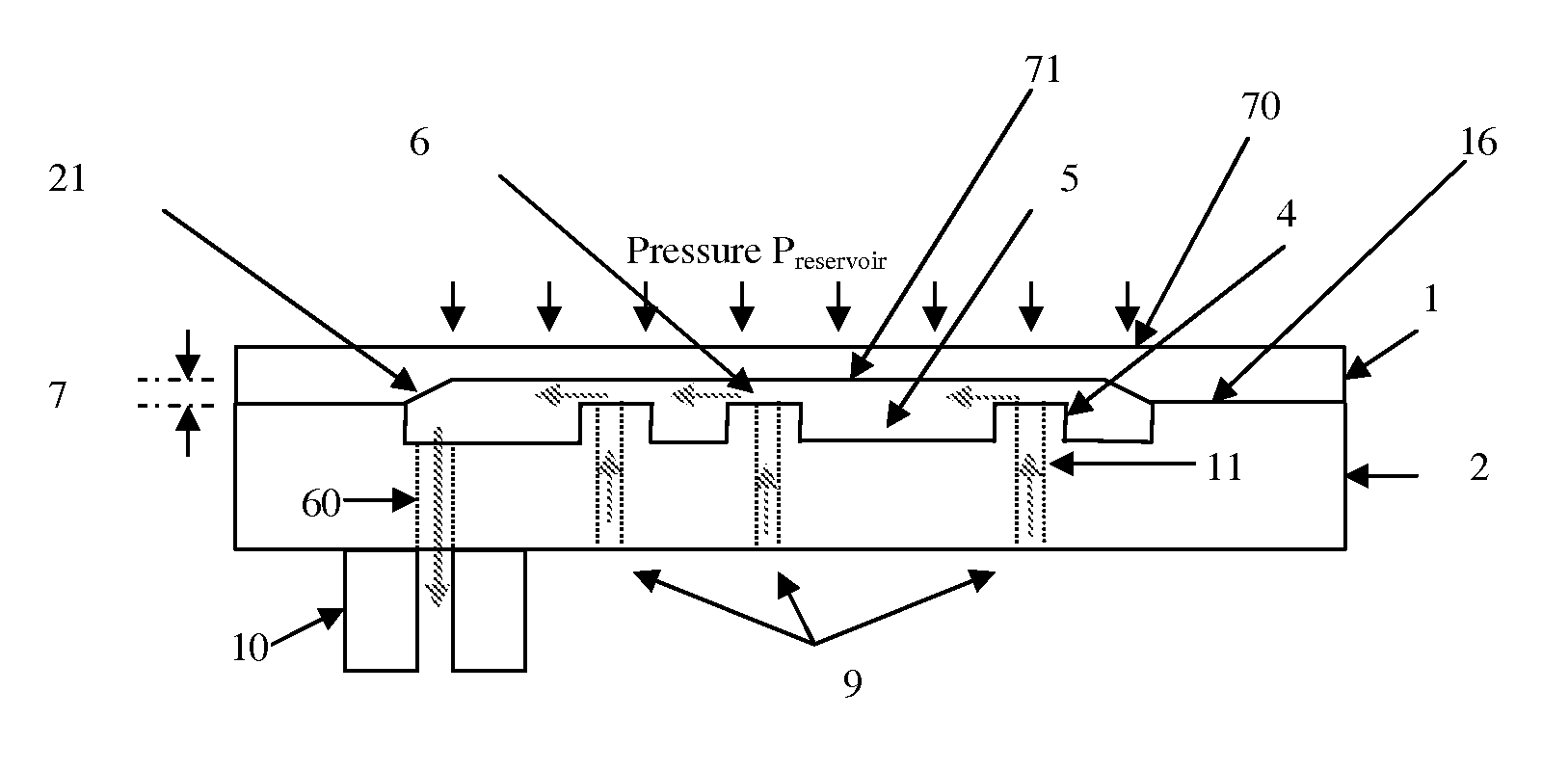
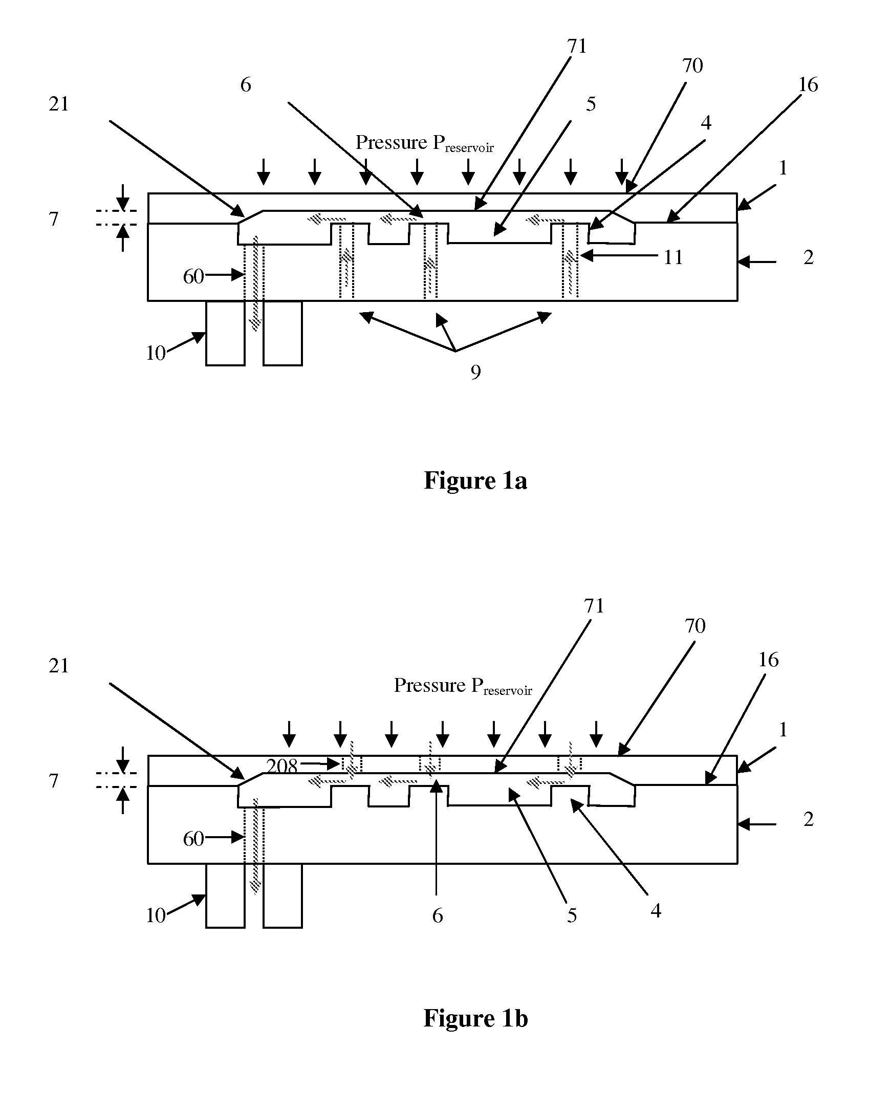
[0058]FIG. 15a shows a simplified plan view of the present invention with additional protective top cap and a fluidic switch in position 1 wherein the pressure is transmitted from the reservoir to only the inlet of the device.

[0059]FIG. 15b shows a simplified plan view of the first embodiment of the present invention with additional protective top cap and a fluidic switch in position 2 wherein the pressure is transmitted from the reservoir to both device inlet and protective cap cavity.

[0060]FIG. 16 shows the simulated flow rate versus pressure characteristic of a passive flow regulator having a silicon membrane according to the dimensions given in table 1.

[0061]FIG. 17 shows the simulated flow rate versus pressure characteristic of a passive flow regulator having a silicon membrane according to the dimensions given in table 2.

[0062]FIG. 18 shows the simulated flow rate versus pressure characteristic of a passive flow regulator having a PMMA membrane according to the dimensions give...

third embodiment

[0128]FIG. 4a shows a first simplified view of flow regulator based on a SOI pillar plate 31.

[0129]Depending on the process yield, all the critical parts may be included into the pillar plate 36 as shown FIG. 4b (e.g. SOI design shown hereafter with the recess 20 etched in the pillar plate 36). The membrane 1 is a simple flat plate without any machining while the bottom plates 3 is another simple flat plate only drilled in order to make the inlet through holes 12. The outlet port 10 could be a connector attached by any means including gluing to the bottom plate 3.

[0130]FIG. 4c shows a third simplified view of the third embodiment of the present invention, wherein both membrane 38 and pillar plates 36 are machined to create the gap 7.

[0131]The pillar plate 37 may also contain no critical part as shown in FIG. 4d. The channel may be obtained by using again by using an SOI wafer for the bottom plate 39.

[0132]In another embodiment the device is only made of two plates, the membrane 1 an...

fifth embodiment

[0151]A simplified pillar plate front view of one of the fifth embodiment is shown FIG. 9a.

[0152]The membrane back-side (etched side) of this another embodiment is shown FIG. 9b. Depending on the process used, the recess 104 or 105 may have a recess wall showing a slope. By using anisotropic wet etch on silicon wafer, the typical recess wall angle is 54.7°.

[0153]The different cavities in the device should be interconnected as shown FIG. 9a with the openings 120. Ideally, the fluidic resistances of these interconnections are designed to ensure that the pressure in all cavities is very close to the outlet pressure.

[0154]The membrane plate 100 can include membranes of any shape including squared, rectangular, elliptical and circular membrane. Membrane of different shapes can be made in the same membrane plate 100.

[0155]In the two preferred embodiments of the present invention, the deformation of the membrane 1 against a pillar plate 2 is used. This effect is strongly non-linear, resu...


PUM


Abstract

The invention concerns a flow regulator, made of a stack of 3 plates, respectively a top plate including a flexible membrane (1), a middle plate (2) with pillars and through holes and a bottom plate (3) with fluidic ports, micro channels and through holes (8,9,12). The principle is based on the deformation of the membrane due to the pressure of the liquid. The membrane goes in contact with the pillars of the middle plate, obstructing gradually the through holes of the pillars. The device is designed to keep the flow constant in a predefined range of pressure. The device is dedicated to ultra low flow rate up to 1 ml per day or below, typically for drug infusion. Plastic flow regulators comprise preferably several independent valves coupled in parallel. The membrane plate is therefore made of several flexible membranes obstructing gradually the flow by increasing the pressure. Stress limiters are used to avoid plastic deformation of the membrane. For implanted pump, the use of a flow regulator instead of a flow restrictor has several advantages, including the possibility to reduce significantly the reservoir pressure and to generate directly the pressure during the pump filling by using an elastic drug reservoir.

Description

FIELD OF THE INVENTION[0001]The present invention relates to fluid flow regulators used in the field of drug delivery, the drug being either liquid or gaseous, for instance for pain management. Such flow regulators can also be used for draining cerebrospinal fluid (CSF) for hydrocephalus patient. The invention further relates to fabrication processes of such flow regulators.STATE OF THE ART[0002]Passive drug infusion devices, in contrast to active ones, do not rely on a pump to deliver a drug but rather on a pressurized drug reservoir. A known problem of these passive devices is that the drug flow rate to a delivery location, which may be a patient's body for instance, may vary as a function of the amount of drug remaining in the reservoir as far as the pressure in the reservoir depends on this amount. Such passive devices are thus usually provided with a fluid flow regulator to ensure that the drug flow rate is as constant as possible with respect to the amount of drug remaining in...

Claims


Application Information

Patent Timeline
Patent Type & Authority Applications(United States)
IPC IPC(8): A61M5/14
CPCA61M5/145A61M27/006F16K99/0001F16K99/0015A61M2039/2413A61M2205/0244F16K2099/0088G05D7/0635F16K2099/008A61M5/16881A61M5/16813F16K99/0057A61M5/14276G05D7/0694Y10T137/7791Y10T137/86734
Inventor CHAPPEL, ERIC
Owner DEBIOTECH SA
Why Eureka
Try Eureka