
Compressor system for vending devices and the like

a vending machine and compressor technology, applied in the field of vending machines, can solve the problems of unacceptably high vending machine temperature, difficulty in determining how, and reduced profit of vending machines, so as to reduce the energy consumption of vending machines and minimize power consumption.

Inactive Publication Date: 2007-06-07
RANCO OF DELAWARE
View PDF35 Cites 85 Cited by
  • Summary
  • Abstract
  • Description
  • Claims
  • Application Information

AI Technical Summary

Benefits of technology

"The present invention provides a new and improved vending machine refrigeration system that decreases energy consumption while ensuring an adequate supply of products at all times. The system utilizes a variable capacity refrigeration unit controlled by an adaptive energy usage profile management and control system that computes the best combination of vertical zone location and number of zones to achieve the most efficient energy demand level based on the thermal characteristic model of the vending device, energy cost, and product demand. The system takes into account real-time data and learning patterns to optimize energy usage and achieve maximum energy savings. The system also includes a watt-hour energy consumption monitoring system and a learning period to establish a baseline thermal characteristic of the unit. The control system is capable of adapting to changes in demand, season, work schedules, and external climate to ensure maximum energy savings."

Problems solved by technology

However, such profitability is reduced by the energy consumption of the vending machine, particularly during periods of inactivity when no consumers are present or purchasing products.
While such a conservation technique is very useful, the difficulty comes in determining how much of the stored product should be kept at the vend temperature to ensure that the supply of cold product is not depleted before the temperature of the remaining products can be brought down to the acceptable temperature.
While such calendar functionality does decrease the energy consumption by the vending machine, it does not account for deviations in usage patterns.
For example, while the calendar function may be set to operate the vending machine in the school cafeteria in the conservation mode during weekends, a weekend sporting event may well result in products being vended at unacceptably high vend temperatures.
This occurs even though the conservation mode of operation typically maintains at least a portion of the products at the proper vend temperature because the rate of consumption of products during such a sporting event will likely exceed the vending machine's ability to cool the products that are stored above the temperature strata where acceptable cooling occurs.
Similarly, energy is wasted during changes in, for example, the school calendar, such as spring break and teachers' institute days.
This is because the simple calendar function does not accommodate changes in the operating schedule even though no one is present on those days.
While such an occupancy sensor is capable of both enhancing the energy savings and ensuring that an ample supply of products are available at the appropriate vend temperature, relying on the mere presence of people within the vicinity of a vending machine to switch to the normal mode of operation may also result in excess energy consumption.
Since most cleaning and security personnel are present during periods that are normally designated by the calendar function as being energy conservation mode periods, the occupancy sensor may well counteract any energy savings that otherwise would have been available via the calendar function.
An additional problem with such systems relates to the refrigeration system that is used in the vending machines.
Energizing the large compressor to accomplish such a relatively small cooling task wastes energy, increases the cycles of the compressor, and increases the overall cost of operation of the vending machine.

Method used


Image

  • Compressor system for vending devices and the like
  • Compressor system for vending devices and the like
  • Compressor system for vending devices and the like

Examples


Embodiment Construction

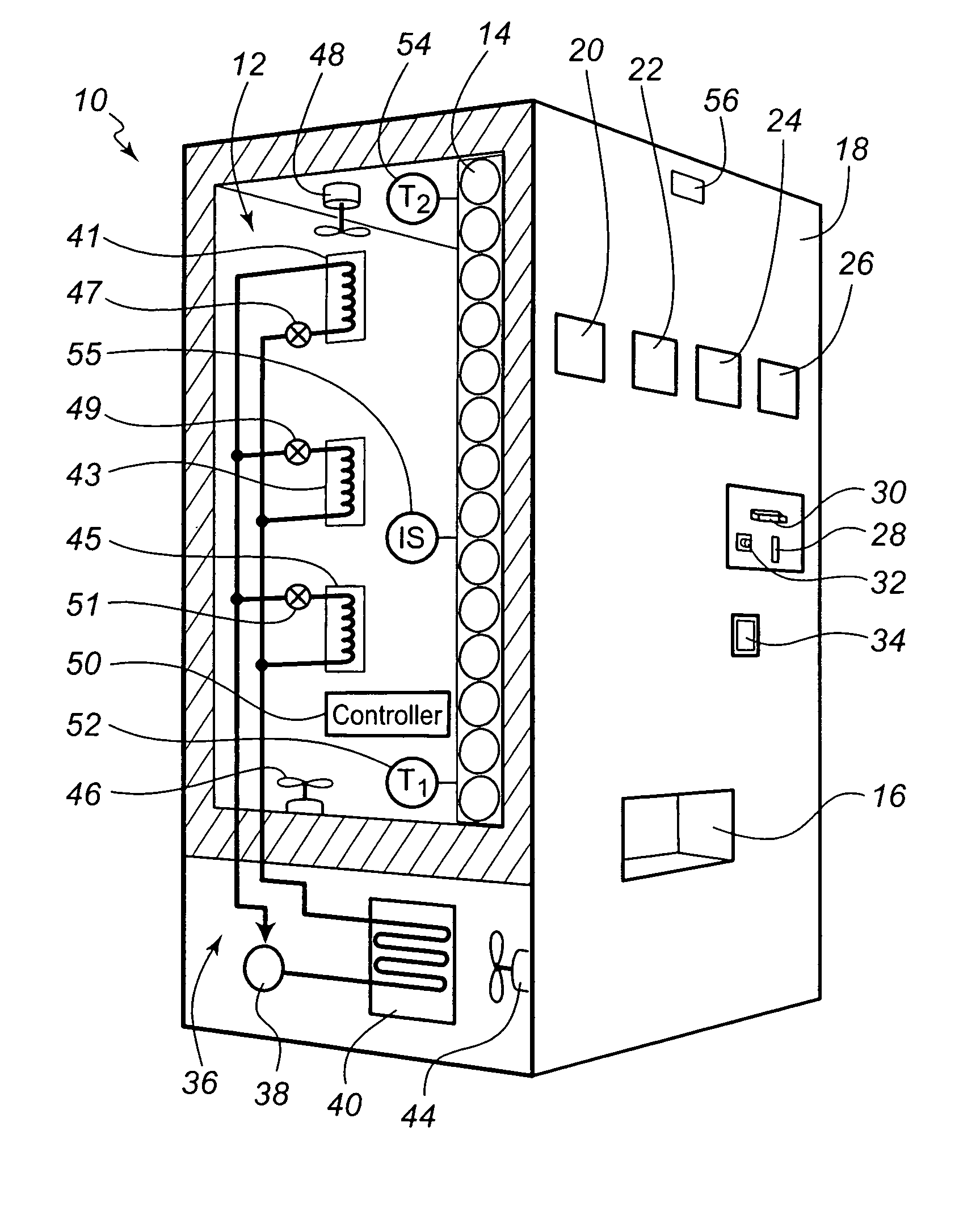
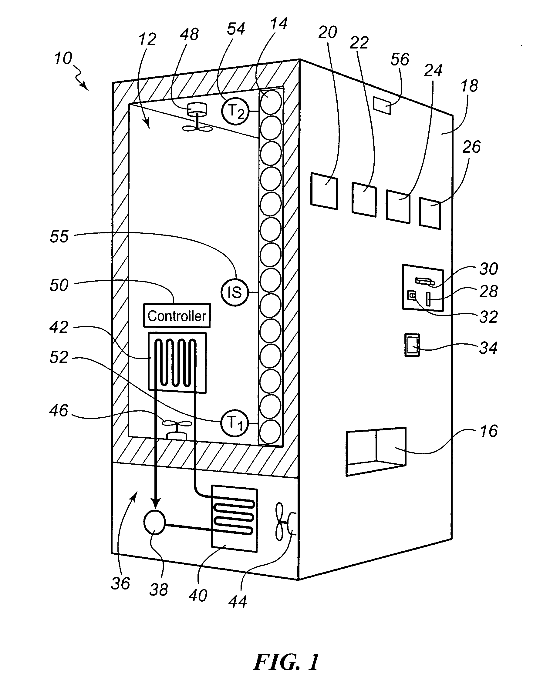
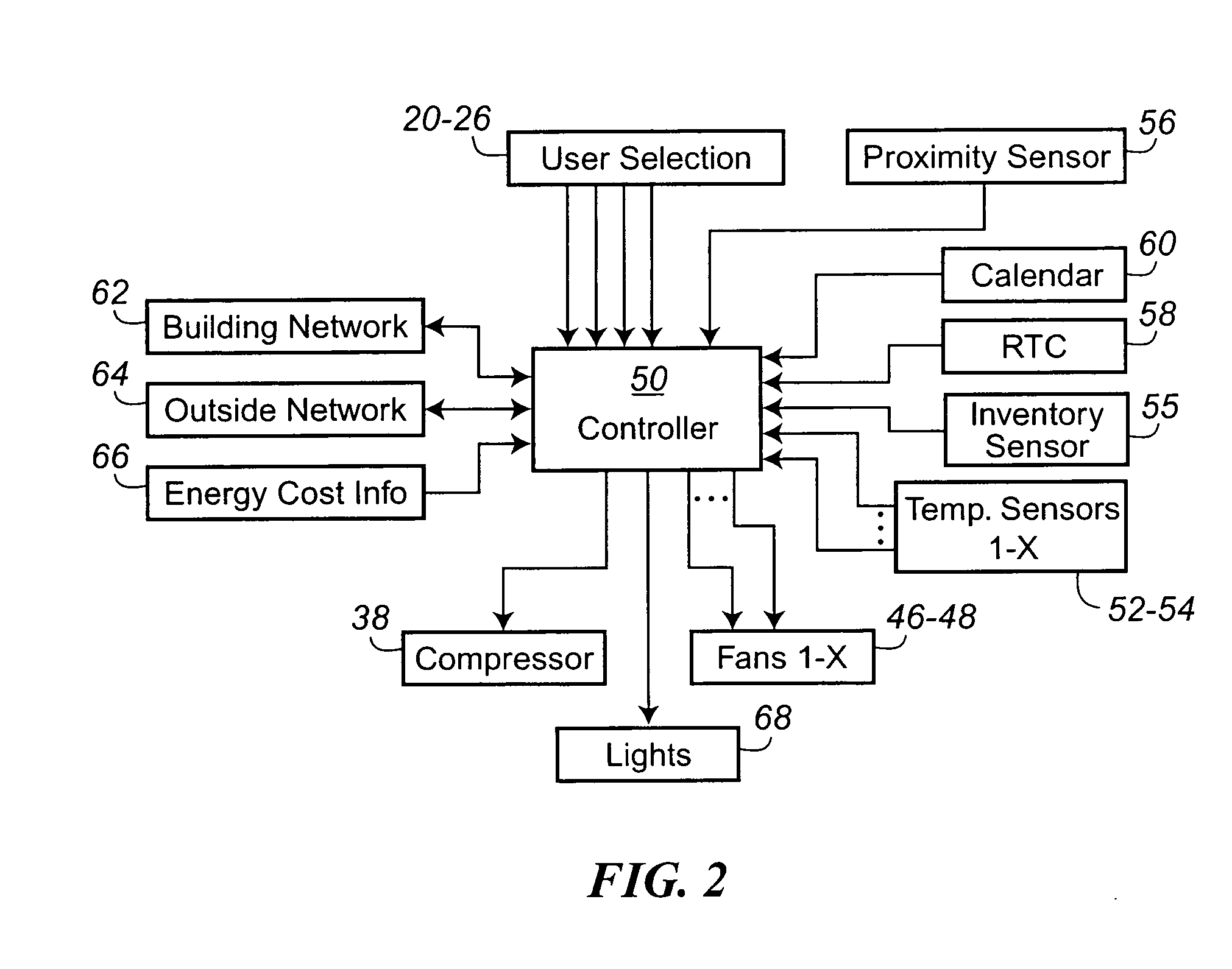
[0038] Turning now to the drawings, there is illustrated in FIG. 1 a simplified partial cut-away illustration of a vending machine for which the system and method of the present invention finds particular applicability. This vending machine 10 includes an insulated product storage compartment 12 in which the products to be vended 14 are stored. For a typical beverage vending machine, the products to be vended 14 are stored in essentially vertical stacks within the storage compartment 12. In this way a gravity feed may supply product to the bottom of the stack from which the product is vended to the dispensing compartment 16, which is typically located on the front panel 18 of the vending machine 10. As will be recognized to those skilled in the art, a particular product is vended in response to user selection of one of a number of product selection buttons 20-26 also located on the front panel 18 of the vending machine 10. The consumer pays for the desired product by inserting money...


PUM


Abstract

An variable capacity compressor system operated by an adaptive energy usage management and thermal control system is provided to reduce the energy consumption and cost of operation of a vending machine. The variable capacity refrigeration system of the present invention includes the use of a variable or multi-speed compressor, a plurality of fixed capacity or speed compressors arranged in a compressor bank, a variable or multi-speed speed compressor with a plurality of refrigeration coils placed in vertical strata levels within the storage compartment, a plurality of fixed capacity or speed compressors arranged in a compressor bank with a plurality of refrigeration coils placed in vertical strata levels within the storage compartment operated by individual refrigerant media control valves, or a plurality of compressors with a plurality of refrigeration coils placed in vertical strata levels within the storage compartment coupled individually to a corresponding compressor, or combinations thereof.

Description

FIELD OF THE INVENTION [0001] The present invention relates generally to vending machines, and more particularly to energy control systems for refrigerated vending machines. BACKGROUND OF THE INVENTION [0002] While the service industry used to rely primarily on face to face, point of purchase contact between service personnel and consumers, the increased pace by which most consumers now operate has driven innovation in the service industry. One such early innovation that has seen tremendous growth is the automated vending machine. While initially confined primarily to break rooms and gas stations, vending machines now have found their way into school cafeterias, dormitories, hotels, office buildings, roadside rests, etc. Indeed, most anywhere there is the availability of electricity and a potential stream of consumers, vending machines may be found. [0003] One reason for the explosive growth of the use of vending machines is that they provide twenty-four hour product availability wi...

Claims


Application Information

Patent Timeline
Patent Type & Authority Applications(United States)
IPC IPC(8): G05D23/32A47F3/04
CPCF25B5/02F25B2400/075F25B2600/0253F25D27/005F25D29/00F25D2700/04F25D2700/06F25D2700/123G07F9/105
Inventor EHLERS, GREGORY ALLEN
Owner RANCO OF DELAWARE
Learn More