Piezoelectric ceramic and laminated piezoelectric element

a piezoelectric element and laminate technology, applied in the field of piezoelectric ceramics, can solve the problems of difficult firing at a temperature as low as 1000° c. or lower, the curie point and the piezoelectric distortion constant become so low, and the desired piezoelectric displacement characteristics are not obtained, etc., to achieve excellent durability and reliability, high piezoelectric distortion constant, and high curie temperature

Inactive Publication Date: 2007-06-07
KYOCERA CORP
View PDF5 Cites 10 Cited by
  • Summary
  • Abstract
  • Description
  • Claims
  • Application Information

AI Technical Summary

Benefits of technology

[0008] It is, therefore, an object of the present invention to provide a piezoelectric ceramic that can be fired at a low temperature, has a high Curie temperature and a high piezoelectric distortion constant, as well as excellent durability and reliability against high temperatures.

Problems solved by technology

However, the piezoelectric ceramic disclosed in the prior art (a) must be fired at a temperature of as very high as 1150° C. to enhance the piezoelectric characteristics, making it difficult to conduct the firing at a temperature of as low as, for example, 1000° C. or lower.
That is, when the firing is conducted at a temperature of 1000° C. or lower, the Curie point and the piezoelectric distortion constant become so low that desired piezoelectric displacement characteristics are not obtained.
Further, a high firing temperature makes it difficult to co-fire the internal electrode layers in combination with the piezoelectric ceramic, which is disadvantageous from the standpoint of lowering the cost.
Therefore, the thus obtained laminated piezoelectric element is accompanied by a problem of low durability and low reliability against high temperatures.
As described above, none of the conventional piezoelectric ceramics simultaneously satisfy the assignments of high piezoelectric characteristics and firing at a low temperature.

Method used


Image

  • Piezoelectric ceramic and laminated piezoelectric element
  • Piezoelectric ceramic and laminated piezoelectric element

Examples


examples

[0095] The invention will now be described by way of the following Experiments.

experiment 1

[0096] Starting powders for piezoelectric ceramics were prepared by weighing the powders of Pb3O4, ZrO2, TiO2, BaCO3, SrCO3, WO3 and Yb2O3 of high purities in predetermined amounts, and wet-mixing the powders in a ball mill having zirconia balls of a diameter of 5 mm for 20 hours. In the starting powders, BaCO3 and SrCO3 were used at a mol ratio of 3:2 as the element M1 of the A-site in the following formula (1),

[Pby-aM1a]·[M2bM3c(Zr1-xTix)1-b-c]·O3+α  (1)

and a was selected to be 0.05. As the element M2 and element M3 of the B-site, there were used WO3 and Yb2O3, respectively, and average valencies of the B-site were set to be as shown in Table 1. In this Experiment, the average valency of the A-site was set to be 2, and the ratio A / B was set to be 1.

[0097] The above starting powders were dehydrated, dried, calcined at 750° C. for 3 hours, and were pulverized to adjust average grain sizes (D50) of the calcined bodies to be not larger than 0.8 μm and BET specific surface areas to b...

experiment 2

[0110] As the starting powder, first, there was used a calcined powder of the composition same as the sample No. 3 of Experiment 1.

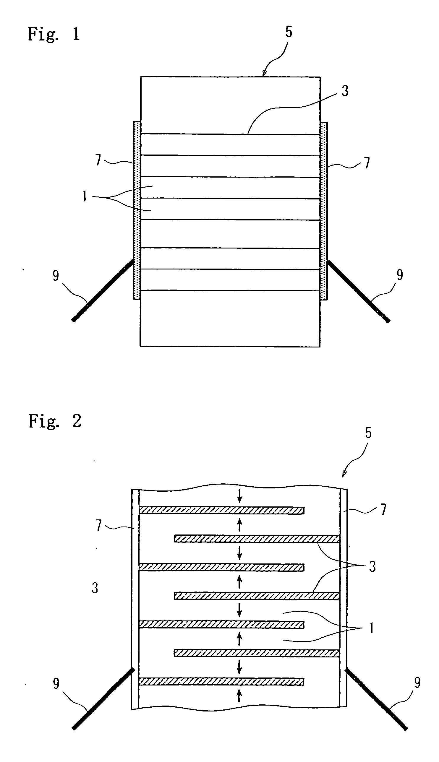
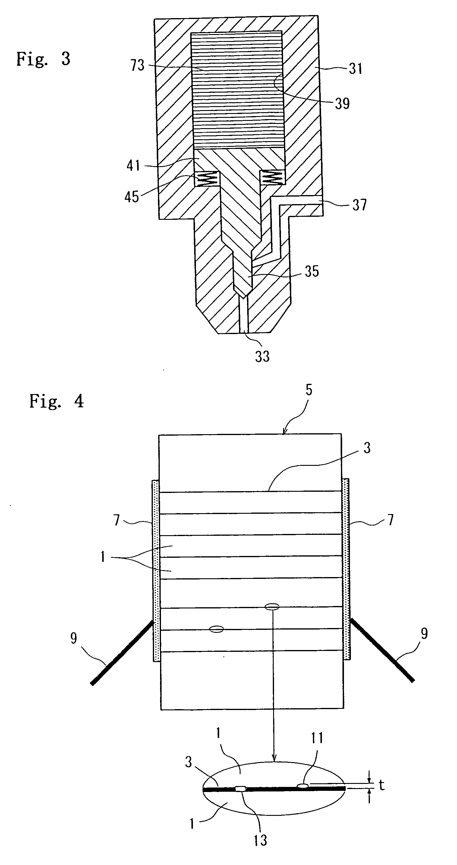
[0111] The calcined powder, an organic binder (polyvinyl butyral) and a plasticizer (DBP) were mixed together to prepare a slurry from which a ceramic green sheet of a thickness of 100 μm was prepared by the slip-casting method. The ceramic green sheet was cut into a desired size, and a conducting paste was printed onto one surface thereof by the screen-printing method such that the thickness thereof was 5 μm and the effective area of the electron pattern was 90% that of the ceramic green sheet after it has been cut.

[0112] The conducting paste was prepared by adding an organic binder (ethyl cellulose) and a plasticizer to a mixed powder of Ag / Pd=95 / 5 (% by mass). For some samples, the starting powder for the piezoelectric ceramic used for forming the green sheet was mixed in an amount of 3% by weight as a base material.

[0113] Next, the conducting patt...


PUM

PropertyMeasurementUnit
grain sizeaaaaaaaaaa
grain size D50aaaaaaaaaa
AC voltageaaaaaaaaaa

Abstract

A piezoelectric ceramic comprising a perovskite composite oxide of an ABO3 composition containing Pb in the A-site and Zr and Ti in the B-site, wherein when the total amount of the element species constituting the B-site of the perovskite composite oxide in the ceramic is set to be one mol, an average valency of the element species constituting the B-site is in a range of from 4.002 to 4.009. The piezoelectric ceramic can be fired at a low temperature, has a high Curie temperature and a high piezoelectric distortion constant, as well as excellent durability and reliability against high temperatures.

Description

TECHNICAL FIELD [0001] The present invention relates to a piezoelectric ceramic and, more specifically, to a piezoelectric ceramic suited for a laminated piezoelectric actuator, a piezoelectric transformer and an ink-jet printer head. BACKGROUND ART [0002] A co-fired laminated piezoelectric element having internal electrodes has heretofore been known, and has been applied to a laminated piezoelectric actuator, a piezoelectric transformer and an ink-jet printer head. The co-fired laminated piezoelectric element is fabricated by co-firing a laminate obtained by alternately laminating ceramic green sheets (that serve as piezoelectric layers) and conducting patterns (that serve as internal electrode layers), and by forming external electrodes thereon, and produces a predetermined displacement by utilizing a counter-piezoelectric effect possessed by the piezoelectric material. [0003] As the piezoelectric ceramic that constitutes piezoelectric layers of the laminated piezoelectric element...

Claims


Application Information

Patent Timeline
Patent Type & Authority Applications(United States)
IPC IPC(8): H01L41/00C04B35/491C04B35/493H01L41/083H01L41/187H01L41/22
CPCB32B18/00B32B2311/08C04B35/491C04B35/493C04B35/6261C04B35/62625C04B35/62675C04B2235/3203C04B2235/3208C04B2235/3213C04B2235/3215C04B2235/3224C04B2235/3225C04B2235/3231C04B2235/3251C04B2235/3258C04B2235/3294C04B2235/5409C04B2235/5445C04B2235/5481C04B2235/6021C04B2235/6025C04B2235/6027C04B2235/786C04B2235/79C04B2237/346C04B2237/348C04B2237/40C04B2237/408C04B2237/706H01L41/083H01L41/0471H01L41/1876H10N30/871H10N30/50H10N30/8554
Inventor KAWAMOTO, TOMOHIROUCHIMURA, HIDEKI
Owner KYOCERA CORP
Why Eureka
Try Eureka