Dual-polarized microstrip patch antenna structure

a microstrip and antenna technology, applied in the direction of antenna earthings, substantially flat resonant elements, resonant antennas, etc., can solve the problems of high assembly cost due to manual labor, low sheet material cost, and mechanical complexity of most dual-polarized dipole antenna configurations, and achieve easy and cost-effective manufacturing, simple structure, and improved input matching

Active Publication Date: 2007-06-07
HMD GLOBAL
View PDF9 Cites 49 Cited by
  • Summary
  • Abstract
  • Description
  • Claims
  • Application Information

AI Technical Summary

Benefits of technology

[0010] The method and system of the invention provide several advantages. The input matching is improved. The antenna structure requires minimal tuning in production. Manufacturing is thus easy and cost-effective. Due to the simple structure, a very...

Problems solved by technology

However, most dual-polarized dipole antenna configurations are mechanically complex due to the required feeding baluns for dipole branches.
This results in high assembly costs due to manual labor, although the sheet material costs are low.
However, the L-probe coupled an...

Method used


Image

  • Dual-polarized microstrip patch antenna structure
  • Dual-polarized microstrip patch antenna structure
  • Dual-polarized microstrip patch antenna structure

Examples


Embodiment Construction

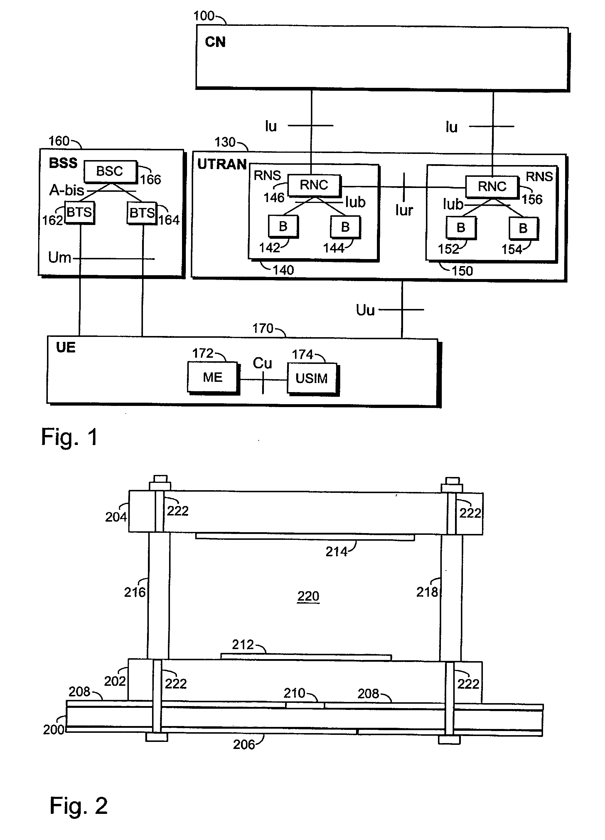
[0019] With reference to FIG. 1, examine an example of a radio system in which the preferred embodiments of the invention can be applied. A radio system in FIG. 1, known at least as UMTS (Universal Mobile Telecommunications System) and IMT-2000 (International Mobile Telecommunications 2000), represents the third-generation radio systems. The embodiments are, however, not restricted to these systems described by way of example, but a person skilled in the art can also apply the instructions to other radio systems containing corresponding characteristics.

[0020]FIG. 1 is a simplified block diagram, which shows the most important parts of a radio system and the interfaces between them at network-element level. The structure and functions of the network elements are not de-scribed in detail, because they are generally known.

[0021] The main parts of a radio system are a core network (CN) 100, a radio access network 130 and user equipment (UE) 170. The term UTRAN is short for UMTS Terres...


PUM


Abstract

A dual-polarized microstrip patch antenna structure comprising: a dual microstrip feed line circuitry underneath a bottom dielectric substrate; a ground plane layer overlying the bottom dielectric substrate, the ground plane layer having coupling apertures etched to the ground plane layer; a middle metallized patch layer stacked over a middle dielectric substrate; a top metallized patch layer stacked underneath a top dielectric substrate; and an air layer between the middle dielectric substrate and the top dielectric substrate separating the middle metallized patch layer and the top metallized patch layer. The microstrip feed line circuitry is configured to utilize corner-feeding techniques for enabling diagonal modes of the patch layers, and the coupling apertures of the ground plane layer are provided with a non-resonant bow-tie shape for enabling aperture coupling between the microstrip feed line circuitry and the patch layers.

Description

FIELD [0001] The invention relates to a dual-polarized microstrip patch antenna structure and to a method of making thereof. BACKGROUND [0002] Modern base station antennas use diversity techniques to reduce the effects of multipath fading. The most common diversity techniques are space and polarization diversities. Space diversity requires that the receiving antennas be placed far from each other so that independent samples of the incoming field are obtained. Hand-held phones transmit at both horizontal and vertical linear polarizations due to tilting of their antennas. The horizontal and vertical polarizations are uncorrelated. Polarization diversity is most commonly achieved by using dual-polarized (typically ±45° slanted polarizations) antennae at the base station. Nowadays, antennas using polarization diversity are preferred due to ease of installation and lower costs over space diversity antennas. [0003] The base station antenna array consists of many antenna elements. The ante...

Claims


Application Information

Patent Timeline
IPC IPC(8): H01Q1/38H01QH01Q9/04
CPCH01Q9/0407H01Q9/0414H01Q9/0435H01Q9/0457
Inventor SAILY, JUSSI
Owner HMD GLOBAL
Why Eureka
Try Eureka