
Audio signal processing device and audio signal reproduction system

a technology of audio signal and processing device, which is applied in the direction of transducer casing/cabinet/support, frequency response correction, electrical transducer, etc., can solve the problems of increased cost, increased cost of preparing the speaker system, and complicated structure of the enclosure 108 of the speaker box

Inactive Publication Date: 2007-06-07
SONY CORP
View PDF9 Cites 32 Cited by
  • Summary
  • Abstract
  • Description
  • Claims
  • Application Information

AI Technical Summary

Benefits of technology

[0017] An object of the present invention is to provide a novel audio signal processing apparatus and a novel audio signal reproducing system which can solve or eliminate problems that prior arts as described above have.
[0018] Another object of the present invention is to provide an audio signal processing apparatus and an audio signal reproducing system in which there is no necessity of allowing drive surfaces of respective drive units to flush with each other in the multiway speaker system to improve delay time difference or differences between speaker units, thus resultantly making it possible to improve sound image localization. MEANS FOR SOLVING THE PROBLEMS

Problems solved by technology

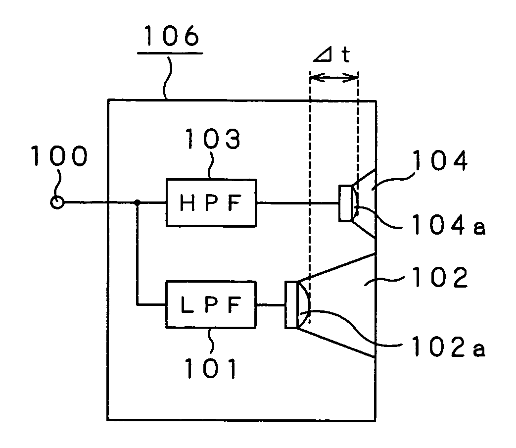
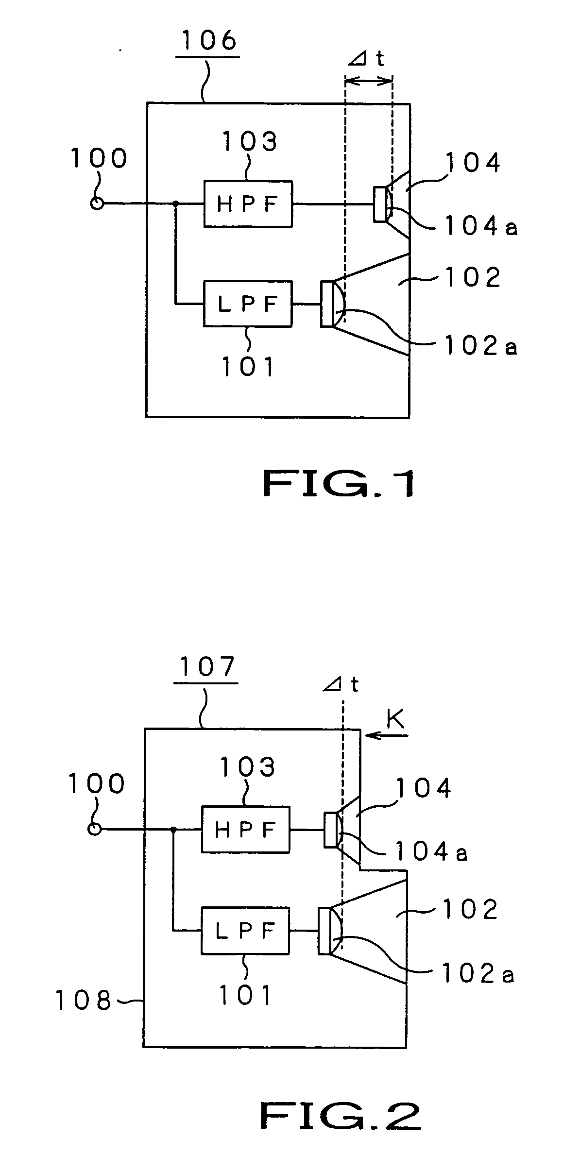
However, since the attachment position of the high frequency drive unit 104 is positionally shifted in a backward direction of the direction indicated by arrow K in FIG. 2, the structure of an enclosure 108 of the speaker box becomes complicated.
For this reason, the cost required for preparing the speaker system is increased.
As a result, the speaker system becomes expensive.
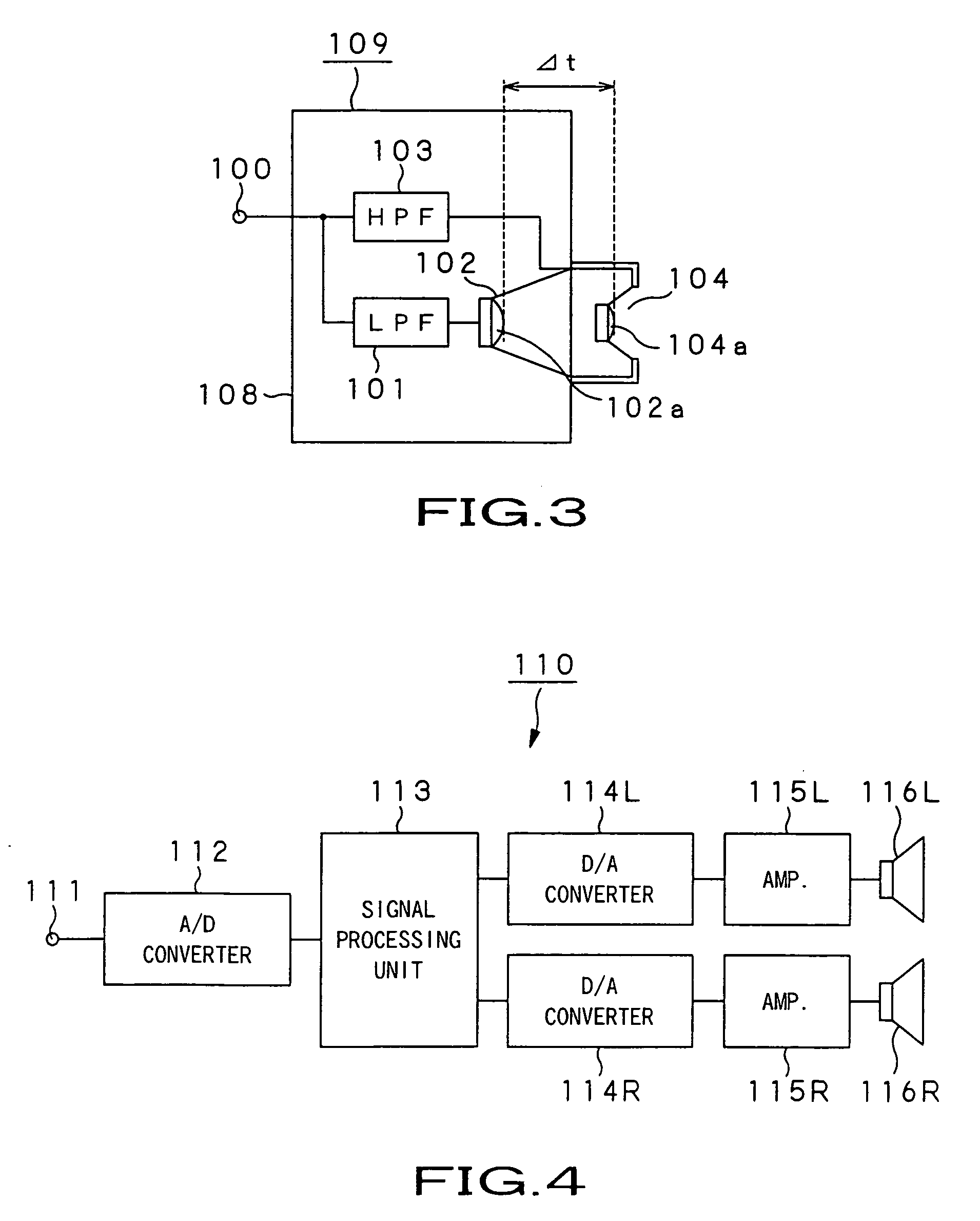
Moreover, there were problems such as deterioration of phase characteristic at crossover frequency based on the characteristic of the divided or separated filters for input signal to respective drive units such as high frequency drive unit 104 and low frequency drive unit 102, etc.
However, there is restriction in the speaker layout.
Thus, there is the problem that listener who can provide a large number of speakers for reproducing sounds of many channels at listening is limited.
In the case where such a method is used, there is the problem that effect may vary depending upon the characteristic of speaker for reproduction.
As a result, there was the problem that sound quality or quality of sound image caused to undergo localization may be deteriorated.
As described above, in the multiway speaker system, there was the problem that when drive surfaces of respective drive units do not flush with each other, since propagation delay time difference takes place at respective reproduction frequency bands so that phases of wave fronts are shifted, there results obstacle to satisfactory sound image localization.
Moreover, in order to avoid the above-mentioned problem, even in the case where there is employed a method in which respective drive units are attached in the state where their drive surfaces are positionally shifted to mechanically adjust phases so that they are flush with each other, there were problems that the cost is increased by complicated attachment structure of speaker units, and / or phase characteristic at crossover frequency is disturbed by band-limit filters with respect to respective speaker units, thus to give bad influence to sound quality and / or sound image localization.
Further, in the system where two speakers are used to allow sound image to undergo localization such that there results an arbitrary position at the outside of the speaker, quality of sound image localization is disadvantageously deteriorated by difference between characteristics of reproduction speakers.

Method used


Image

  • Audio signal processing device and audio signal reproduction system
  • Audio signal processing device and audio signal reproduction system
  • Audio signal processing device and audio signal reproduction system

Examples


first embodiment

[0063] The first embodiment is directed to an audio signal reproducing system 1 as shown in FIG. 6. While explanation will be given in the audio signal reproducing system 1 on the assumption that digital audio signal is handled as input signal, analog audio signal can be similarly handled by initially performing A / D converting processing.

[0064] In FIG. 6, the audio signal reproducing system 1 comprises a signal processing unit (apparatus) 3 for adding characteristic which will be described later to a digital audio signal inputted from an input terminal 2, a D / A converter 4 for converting a processed output from the signal processing unit 3 into an analog signal, a power amplifier 5 for amplifying the analog signal from the D / A converter 4, and a two-way speaker system 7 composed of a unit for driving a signal at low frequency band (hereinafter simply referred to as a low frequency drive unit or driver) 9 connected to a LPF8 and a unit for driving a signal at high frequency band (her...

second embodiment

[0081] As a result, the audio signal reproducing system 30 of the second embodiment serves to allow the signal processing unit 31 to function (perform) processing shown in FIGS. 12 and 13 to exclude impulse response specific to the multiway speaker system in speaker output to have ability to provide an only output in which the group delay characteristic is constant. Thus, also in the case where an arbitrary frequency characteristic is added, there would result no possibility that phase is shifted by a specific frequency. As a result, it is possible to obtain multiway speaker system excellent in both sound quality and sound image localization.

[0082] Then, the third embodiment according to the present invention will be explained. The third embodiment is directed to an audio signal reproducing system 40 of the configuration shown in FIG. 15 in which two speakers are used to constitute virtual speaker sound source to allow sound image to undergo localization such that there results an a...


PUM


Abstract

The present invention is directed to an audio signal reproducing system comprising a speaker system including at least two drive units or more which are divided or separated by frequency band. In this system (1), a signal processing unit (3) serves to add inverse characteristic to an inputted digital audio signal as correction characteristic of impulse response of speaker system (7). Thereafter, a D / A converter converts the digital audio signal thus obtained back into an analog signal. A power amplifier (5) amplifiers the analog signal thus obtained to deliver the analog signal thus amplified to the speaker system (7). The speaker system (7) outputs a signal at low frequency band that a LPF (8) has passed as sound wave of low pitched sound from drive surface (9a) of a low frequency drive unit (9), and outputs a signal at high frequency band that a HPF (10) has passed as sound wave of high pitched sound from drive surface (11a) of a high frequency drive unit (11).

Description

TECHNICAL FIELD [0001] The present invention relates to a speaker and headphone system which have satisfactory sound image localization characteristic, and an audio signal processing apparatus and an audio signal reproducing system in the case of allowing satisfactory sound image to undergo localization such that there results an arbitrary position. [0002] This Application claims priority of Japanese Patent Application No. 2003-417334, filed on Dec. 15, 2003, the entirety of which is incorporated by reference herein. BACKGROUND ART [0003] In the case of reproducing an audio or acoustic signal by a speaker unit, in order to obtain satisfactory frequency characteristic over a broad frequency band, since frequency bands in which satisfactorily reproduction can be performed are different from each other in accordance with respective apertures every drive units or speaker units, there is used multiway speaker system including plural drive units such as woofer, tweeter and / or super-tweete...

Claims


Application Information

Patent Timeline
IPC IPC(8): H03G5/00H04R1/26H04R1/28H04R1/40H04R3/14H04S1/00H04S7/00
CPCH04R1/24H04R3/04H04S1/007H04S2400/01H04R1/20H04R3/12H04S1/00H04S7/00
Inventor YAMADA, YUJIOKIMOTO, KOYURU
Owner SONY CORP
Learn More