
Open loop polar transmitter having on-chip calibration

a polar transmitter and open loop technology, applied in the field of open loop polar transmitter on-chip calibration, can solve the problems of consuming significantly more power, inefficient highly linear power amplifiers, and difficult to adapt existing gsm modulation schemes to transmit signals

Inactive Publication Date: 2007-06-07
SKYWORKS SOLUTIONS INC
View PDF2 Cites 64 Cited by
  • Summary
  • Abstract
  • Description
  • Claims
  • Application Information

AI Technical Summary

Problems solved by technology

Unfortunately, existing GSM modulation schemes are not easily adapted to transmit a signal that includes both a PM component and an AM component.
Unfortunately, highly linear power amplifiers are very inefficient, thus consuming significantly more power than a non-linear power amplifier and drastically reducing the life of the battery or other power source.
However, due to stringent requirements for modulation accuracy and spectral purity, as well as output power range and control accuracy, the open loop architecture faces design challenges.
Unfortunately, this typically requires that the power output characteristics of each transmitter be determined and calibrated when the transmitter is built.
This consumes valuable manufacturing and testing resources, and does not take into account long term changes to the characteristics of the transmitter as it ages.

Method used


Image

  • Open loop polar transmitter having on-chip calibration
  • Open loop polar transmitter having on-chip calibration
  • Open loop polar transmitter having on-chip calibration

Examples


Embodiment Construction

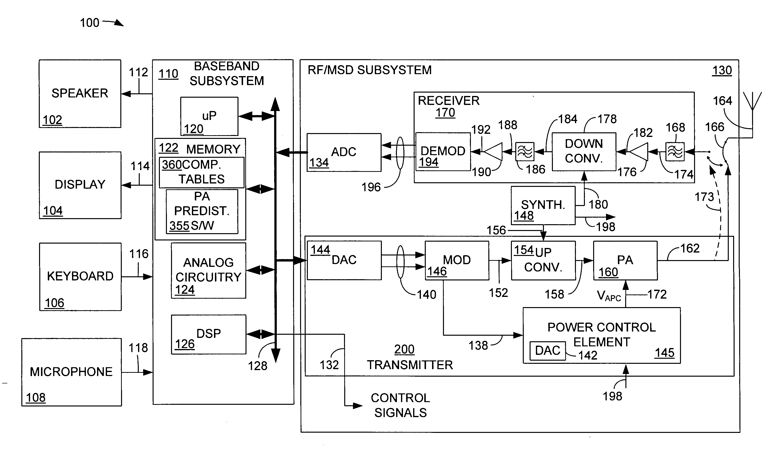
[0018] Although described with particular reference to a portable transceiver, the open loop polar transmitter having on-chip calibration can be implemented in any system in which a transmitted signal includes both an AM component and a PM component, and in which the AM component is applied to the control port of the power amplifier.

[0019] The open loop polar transmitter having on-chip calibration can be implemented in hardware, software, or a combination of hardware and software. When implemented in hardware, the open loop polar transmitter having on-chip calibration can be implemented using specialized hardware elements and logic. When the open loop polar transmitter having on-chip calibration is implemented partially in software, the software portion can be used to adaptively apply the AM and PM pre-distortion to the transmitter, thereby compensating for the AM and PM characteristics during normal use of the transmitter, if these characteristics should change as a function of te...


PUM


Abstract

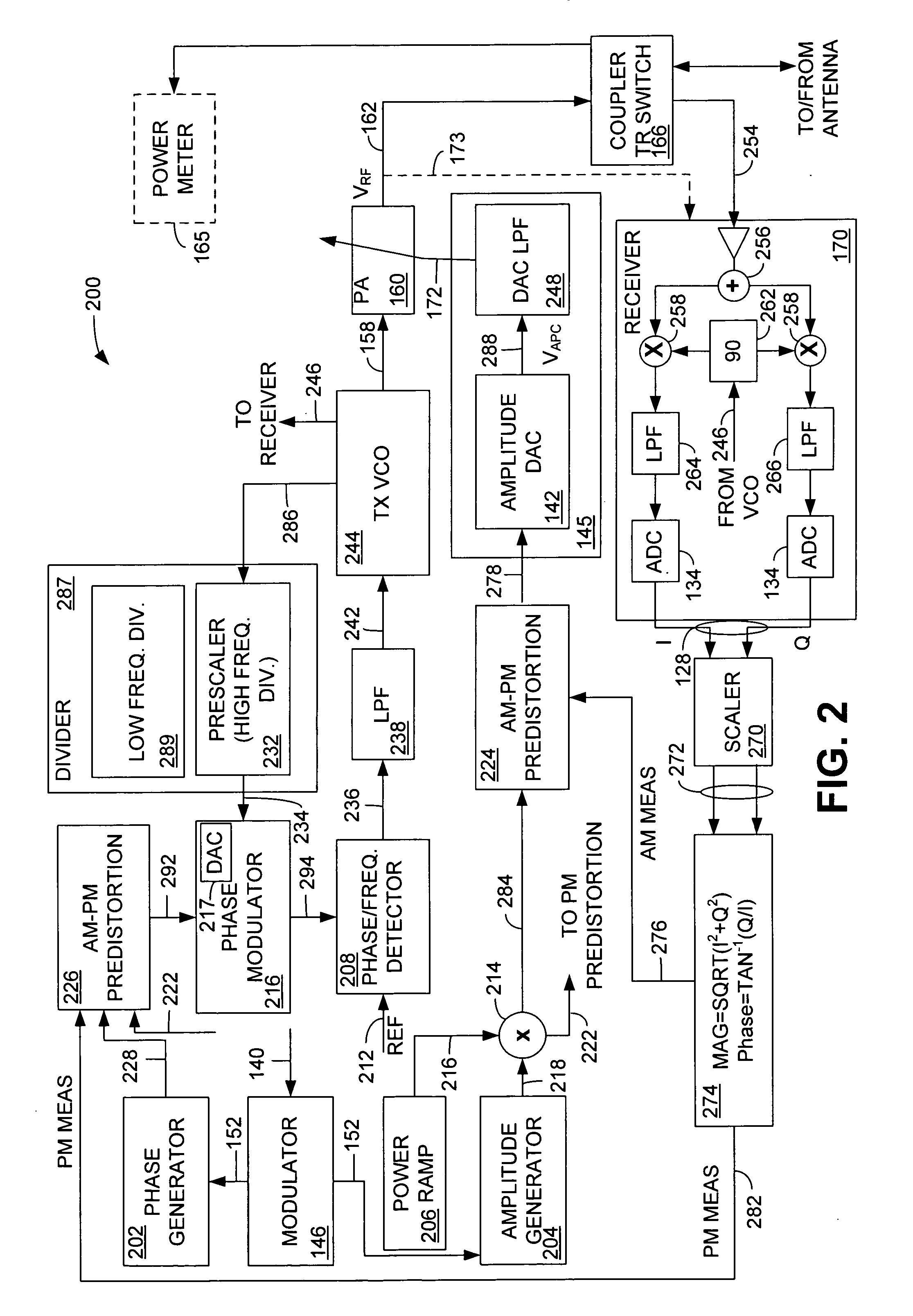
An on-chip calibration system comprises a transmitter, a receiver, a phase and amplitude determination element configured to determine amplitude and phase characteristics of an output signal generated in the transmitter, the signal representing transmitter characteristics, an amplitude comparison element configured to compare the signal representing transmitter characteristics with a desired amplitude signal and generate an amplitude compensation signal, an AM predistortion element configured to modify an ideal AM signal with the amplitude compensation signal, a phase comparison element configured to compare the signal representing transmitter characteristics with a desired phase signal and generate a phase compensation signal, and a PM predistortion element configured to modify an ideal phase signal with the phase compensation signal.

Description

BACKGROUND OF THE INVENTION [0001] 1. Field of the Invention [0002] This invention relates generally to transceiver architecture in a wireless portable communication device. More particularly, the invention relates to a system for on-chip calibration of an open-loop polar loop transmitter. [0003] 2. Related Art [0004] Radio frequency (RF) transmitters are found in many one-way and two-way communication devices, such as portable communication devices, (cellular telephones), personal digital assistants (PDAs) and other communication devices. An RF transmitter must transmit using whatever communication methodology is dictated by the particular communication system within which it is operating. For example, communication methodologies typically include amplitude modulation, frequency modulation, phase modulation, or a combination of these. In a typical GSM mobile communication system using narrowband TDMA technology, a GMSK modulation scheme supplies a low noise phase modulated (PM) tra...

Claims


Application Information

Patent Timeline
Patent Type & Authority Applications(United States)
IPC IPC(8): H04B1/04
CPCH04B1/0475H04B2001/0425H04B2001/0433H03F1/3241H03F1/34H03F3/24
Inventor VASA, JOHN E.DOMINO, WILLIAM J.BEAMISH, NORMAN J.DAMGAARD, MORTEN
Owner SKYWORKS SOLUTIONS INC
Learn More