Polar transmitter using binary phase shift key (BPSK) modulation method

a technology of phase shift key and polar transmitter, which is applied in the direction of phase-modulated carrier system, digital transmission, multiple carrier system, etc., can solve the problems of signal quality reduction, complex circuit construction, and difficulty in adjustmen

Inactive Publication Date: 2007-12-27
SAMSUNG ELECTRONICS CO LTD
View PDF11 Cites 18 Cited by
  • Summary
  • Abstract
  • Description
  • Claims
  • Application Information

AI Technical Summary

Benefits of technology

[0020]An aspect of the present invention is to provide a polar transmitter using a binary phase shift key (BPSK) modulation method, which is capable of processing data at a high speed, thereby allowing the polar transmitter to be applicable to multimode and a multiband applications, and simplifying circuit construction.
[0032]The second delaying unit may delay the phase component by a time required for processing the amplitude component at the second pulse shaping filter.

Problems solved by technology

Such a super heterodyne type transmitter is disadvantageous in that circuit parts are large in number, so that circuit construction is complicated and adjustments are difficult.
Also, the direct conversion type transmitter presents a problem in that a signal is lowered in quality due to a noise by a DC component and a mismatching between an I signal and a Q signal.
As a result, an entire modulation time for outputting the carrier wave is increased, and circuit construction is complicated.
However, this design results in an increase in size and cost, and a reduction in design efficiency.
However, since the feedback circuit of the PLL 20 results in the time delay, it is not adapted to use the PLL 20 in a multi-band system.

Method used


Image

  • Polar transmitter using binary phase shift key (BPSK) modulation method
  • Polar transmitter using binary phase shift key (BPSK) modulation method
  • Polar transmitter using binary phase shift key (BPSK) modulation method

Examples


Embodiment Construction

[0049]The matters defined in the description such as a detailed construction and elements are provided to assist in a comprehensive understanding of the exemplary embodiment of the invention and are merely exemplary. Accordingly, those of ordinary skill in the art will recognize that various changes and modifications of the exemplary embodiment described herein can be made without departing from the scope and spirit of the invention. Also, descriptions of well-known functions and constructions are omitted for clarity and conciseness.

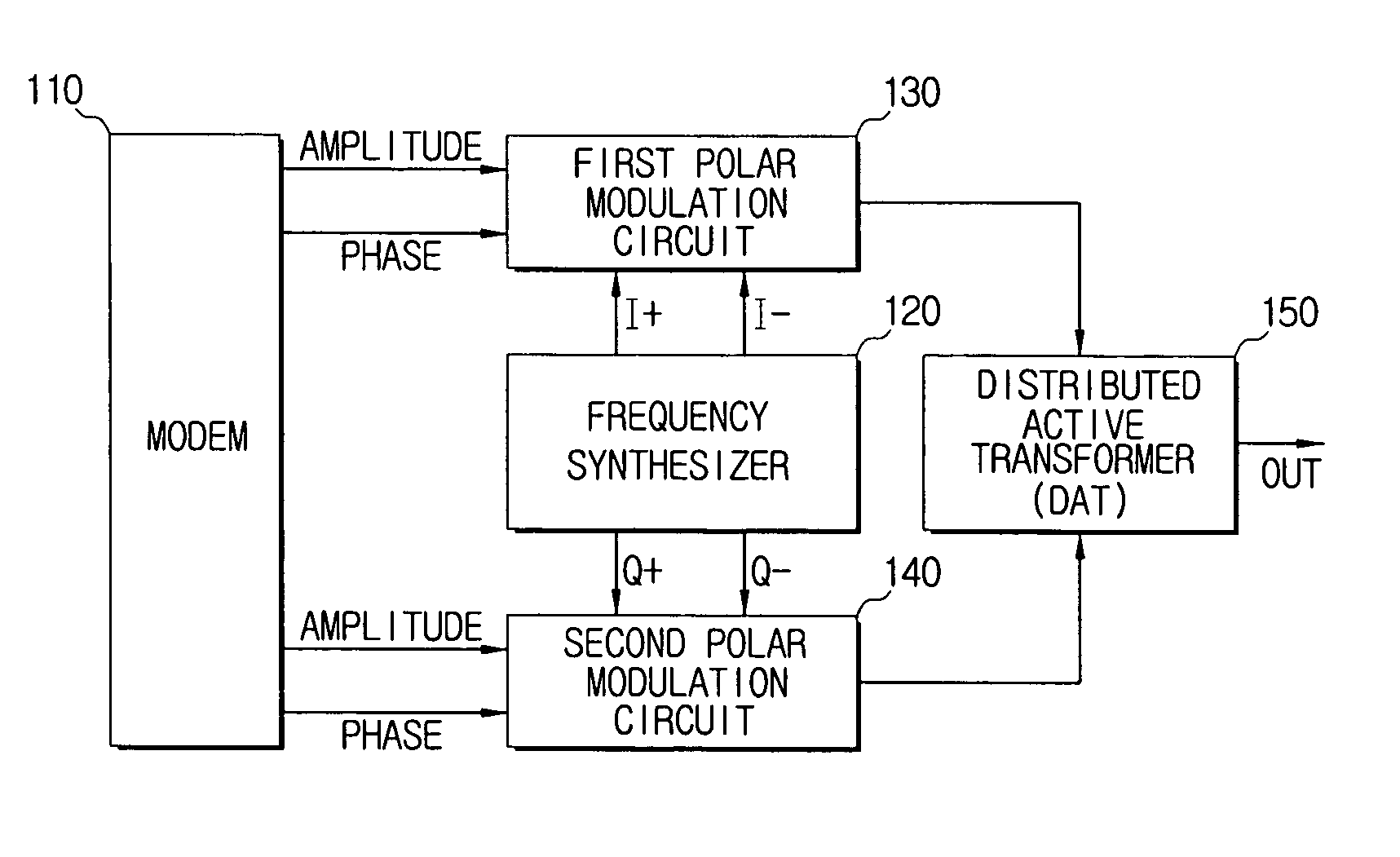
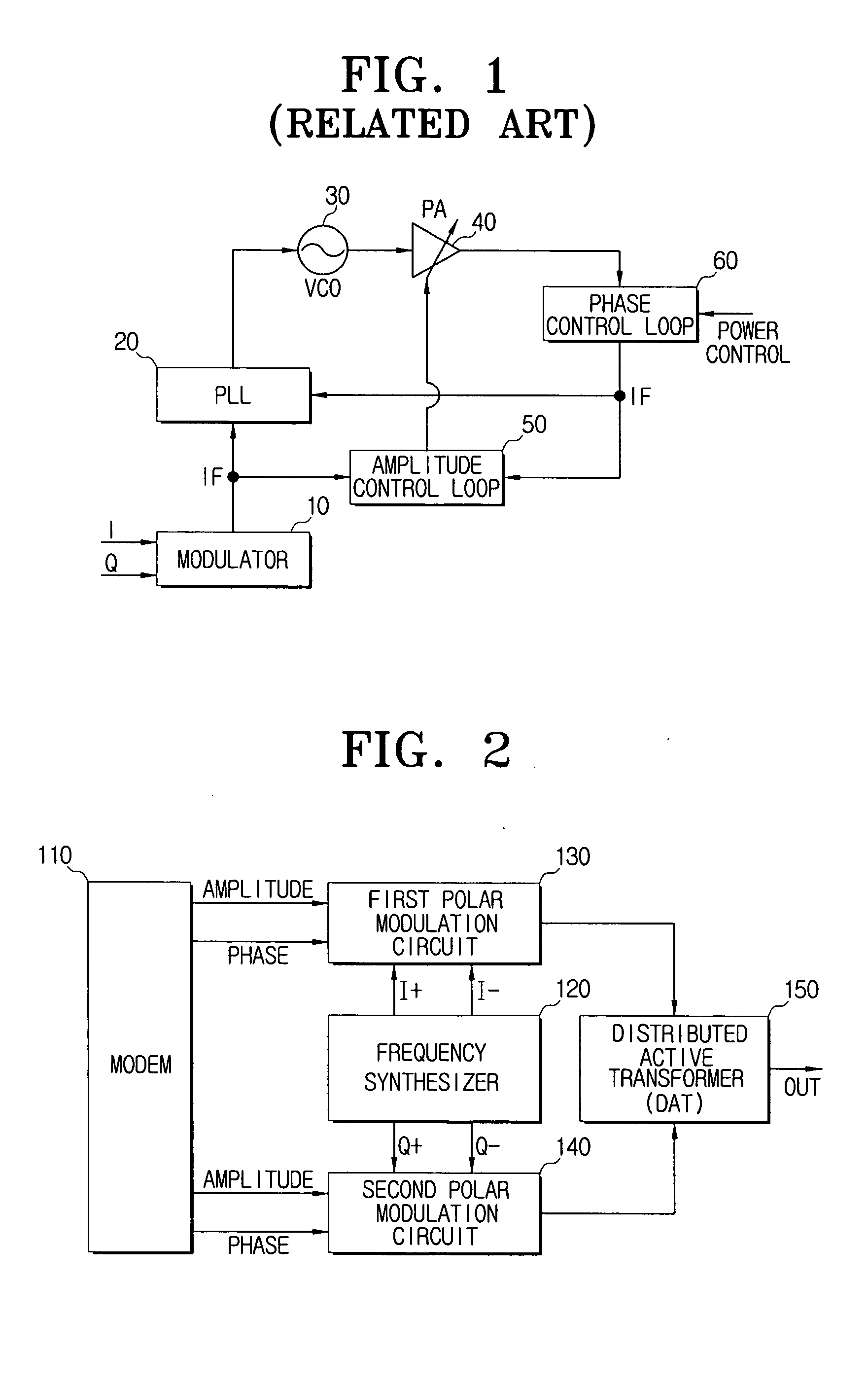
[0050]FIG. 2 is a schematic circuit diagram exemplifying a polar transmitter according to an exemplary embodiment of the present invention.

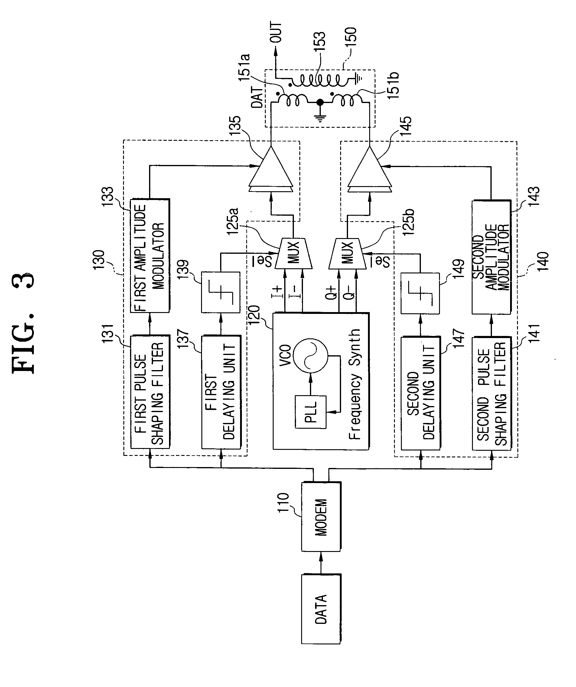
[0051]The polar transmitter according to the exemplary embodiment of the present invention includes a modem 110, a frequency synthesizer 120, a polar modulation circuit for the I signal 130, a polar modulation circuit for the Q signal 140, and a distributed active transformer (DAT) 150.

[0052]The modem 110 divides data...


PUM


Abstract

A polar transmitter using a binary phase shift key (BPSK) method includes a data dividing unit which divides input data into an amplitude component and a phase component, a frequency synthesizer which produces an I value of a passband having a phase component of an I signal and a Q value of a passband having a phase component of a Q signal, a polar modulation circuit for the I signal which produces an I carrier wave to the I signal using the amplitude component from the data dividing unit and the I value from the frequency synthesizer, a polar modulation circuit for the Q signal which produces a Q carrier wave to the Q signal using the amplitude component and the Q value, and a carrier wave producing unit which combines the I carrier wave and the Q carrier wave thus to produce a carrier wave.

Description

CROSS-REFERENCE TO RELATED APPLICATIONS[0001]This application claims priority under 35 U.S.C. §119(a) of Korean Patent Application No. 10-2006-054735, filed Jun. 19, 2006, in the Korean Intellectual Property Office, the entire disclosure of which is incorporated herein by reference.FIELD OF THE INVENTION[0002]Apparatuses and methods consistent with the present invention relate generally to a polar transmitter using a binary phase shift key (BPSK) modulation method in which a distributed active transformer (DAT) is mounted. More particularly, the present invention relates to a polar transmitter using a BPSK modulation method in which a DAT is mounted, and which can process data at a high speed, thereby allowing the polar transmitter to apply to multimode and multiband applications and uses a BPSK modulation method to simplify circuit construction.BACKGROUND OF THE INVENTION[0003]Generally, a spread spectrum type transmitter mainly uses a sine wave, a pulse wave, etc. as a carrier wav...

Claims


Application Information

Patent Timeline
Patent Type & Authority Applications(United States)
IPC IPC(8): H04B1/02H04B1/66
CPCH04L27/362H04L27/32H04L27/18H04L27/20
Inventor LEE, JEONG-HOONKIM, SEUNG-WOOLEE, JAE-SUPPARK, EUN-CHULKIM, YOUNG-SIK
Owner SAMSUNG ELECTRONICS CO LTD
Why Eureka
Try Eureka