Automatic vehicle braking device

Inactive Publication Date: 2007-06-07
MITSUBISHI ELECTRIC CORP
View PDF30 Cites 41 Cited by
  • Summary
  • Abstract
  • Description
  • Claims
  • Application Information

AI Technical Summary

Benefits of technology

[0012] According to the present invention, there is provided an automatic vehicle braking device including: detection means for detecting a relative distance, lateral position, and speed of an obstacle with respect to one's vehicle; collision judgment means for making a judgement as to whether a possibility of collision of one's vehicle and the obstacle exists based on detection values obtained by the detection means; steering operation detecting means for detecting a steering operation by a driver; and braking force control means for causing a braking force to be exerted on each wheel to brake the vehi

Problems solved by technology

However, the conventional device as disclosed in JP 2005-041465 A has the following problem.
The conventional device as disclosed in JP 2005-28992 A has a problem in that no consideration is taken of how to cope with a situation in which the driver takes a steering avoi

Method used


Image

  • Automatic vehicle braking device
  • Automatic vehicle braking device
  • Automatic vehicle braking device

Examples


embodiment 1

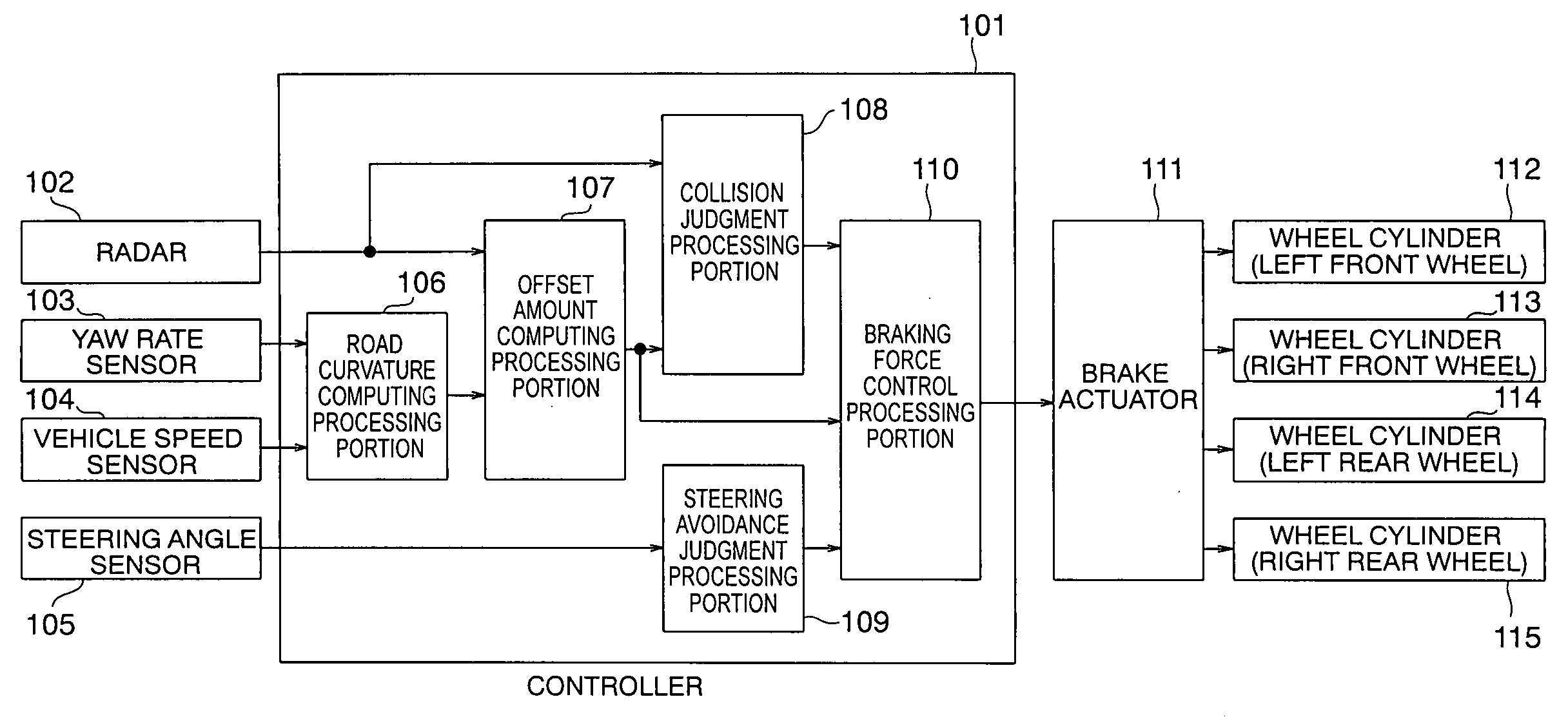
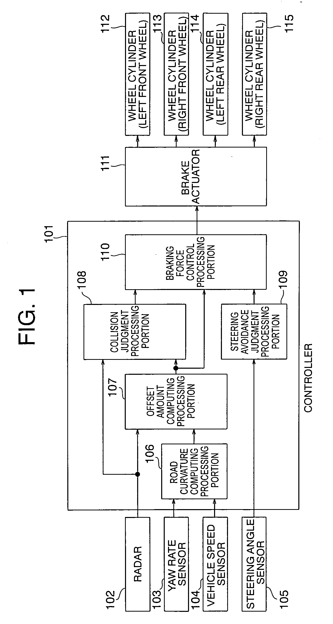
[0034] An automatic vehicle braking device according to Embodiment 1 of the present invention will be described. FIG. 1 shows a construction of the automatic vehicle braking device of this embodiment. As shown in FIG. 1, connected to a controller 101 are a radar 102, a yaw rate sensor 103, a vehicle speed sensor 104, and a steering angle sensor 105.

[0035] Based on input information from the various sensors 102 through 105 externally connected to the controller 101, the controller 101 executes a computation for controlling various externally connected actuators described below.

[0036] The radar 102 serves to measure the relative distance, lateral position, and speed with respect to one's vehicle of each of a plurality of obstacles existing within a specific range ahead of one's vehicle.

[0037] The yaw rate sensor 103 is a sensor for detecting the yaw rate of one's vehicle.

[0038] The vehicle speed sensor 104 is a sensor for detecting the speed of one's vehicle.

[0039] The steering a...

embodiment 2

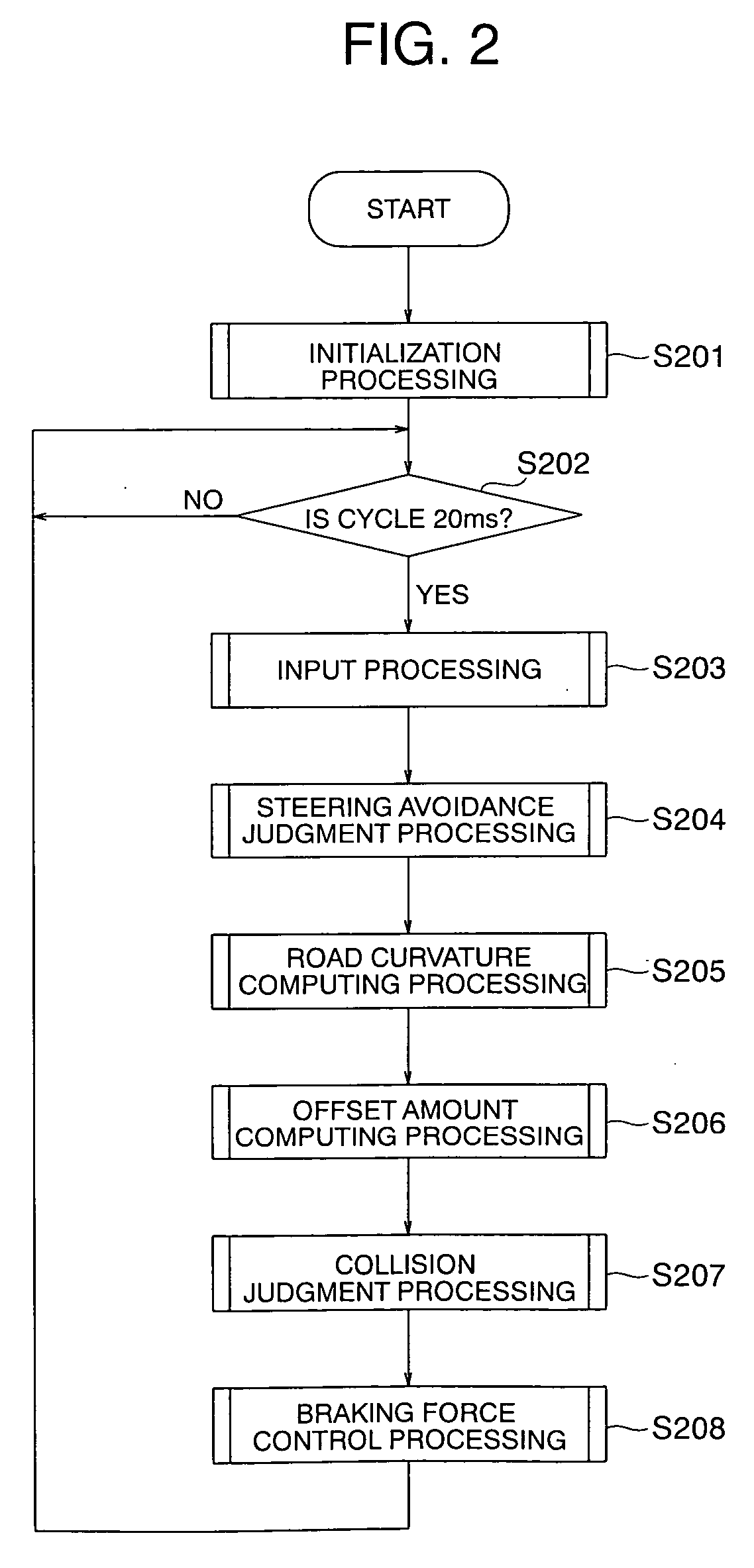
[0075] The device construction of this embodiment is the same as that of FIG. 1, so a description of the device construction of this embodiment will be omitted. Further, the processing flow is the same as that of FIG. 2 except for the braking force control processing of step S208.

[0076] The braking force control processing of step S208 of this embodiment will be described in detail. FIG. 8 is a detailed flowchart illustrating the processing.

[0077] First, in step S701, using the judgment result of the steering avoidance judgment processing of step S204, a judgment is made as to whether the driver is performing steering avoidance or not. When the driver is performing steering avoidance, it is determined that there is no need to operate the device, and the procedure advances to step S704. Otherwise, the procedure advances to step S702.

[0078] In step S702, the judgment result of the collision judgment processing of step S207 is used to make a judgment as to whether the possibility of...

embodiment 3

[0087]FIG. 10 shows a construction of an automatic vehicle control device according to this embodiment. The components of this device are as shown in the figure. As shown in FIG. 10, connected to a controller 801 are a radar 802, a yaw rate sensor 803, a vehicle speed sensor 804, and a steering angle sensor 805.

[0088] Based on input information from the externally connected various sensors, the controller 801 executes a computation for controlling various actuators which are also externally connected.

[0089] The radar 802 serves to measure the relative distance, lateral position, and speed with respect to one's vehicle of each of a plurality of obstacles existing within a specific range ahead of one's vehicle.

[0090] The yaw rate sensor 803 is a sensor for detecting the yaw rate of one's vehicle.

[0091] The vehicle speed sensor 804 is a sensor for detecting the speed of one's vehicle.

[0092] The steering angle sensor 805 is a sensor for detecting a steering angle attained through o...


PUM


Abstract

The automatic vehicle braking device is equipped with a braking force control processing portion which, based on the judgment result of a collision judgment processing portion and the judgment result of a steering avoidance judgment processing portion, imparts a turning property in a direction of head-on collision to the vehicle when the lateral position of the obstacle with respect to a travel route curve is large in a condition in which the driver is unconscious of a high possibility of collision between the vehicle and the obstacle and has taken no steering avoidance action yet. As a result, it is possible to reduce the speed of the vehicle and, at the same time, mitigate the damage suffered by the vehicle occupants at the time of collision.

Description

BACKGROUND OF THE INVENTION [0001] 1. Field of the Invention [0002] The present invention relates to an automatic vehicle braking device, in particular, an automatic vehicle braking device for automatically braking a vehicle when there is a possibility of collision between the vehicle and an obstacle. [0003] 2. Description of the Related Art [0004] Vehicle travel safety devices have conventionally been proposed. For example, there has been proposed a device in which travel environment factors about a vehicle, more specifically, the distance (inter-vehicle distance) to a vehicle ahead and the relative speed of the vehicle ahead with respect to one's vehicle are detected. When the distance between one s vehicle and the obstacle (the vehicle ahead) has become smaller than a predetermined distance, there is generated a deceleration (primary braking) capable of letting the driver know that a braking force has been generated by an automatic brake device. When the state in which the distan...

Claims


Application Information

Patent Timeline
IPC IPC(8): G06F17/10
CPCB60T7/22B60W10/18B60W10/196B60W2550/20B60W2554/00
Inventor YANO, TAKUTOTANIGUCHI, SHINJISHIMIZU, YUJIYUYAMA, ATSUSHI
Owner MITSUBISHI ELECTRIC CORP
Why Eureka
Try Eureka