Wafer support system

a support system and wafer technology, applied in the direction of crystal growth process, semiconductor/solid-state device details, manufacturing tools, etc., can solve the problems of unfavorable conductive heat transfer

Inactive Publication Date: 2007-06-14
ASM AMERICA INC
View PDF90 Cites 28 Cited by
  • Summary
  • Abstract
  • Description
  • Claims
  • Application Information

AI Technical Summary

Benefits of technology

[0011] The present invention embodies a susceptor which supports a wafer spaced therefrom and effectively decouples conductive heat transfer between the two elements. The wafer is supported on one or more spacers in a recess preferably in an upper surface of the susceptor, the top plane of the wafers preferably being approximately level with an outer ledge of the susceptor. The susceptor preferably includes a plurality of interior passages opening into the recess at a plurality of small sweep gas holes. A sweep gas flows through the susceptor and out the holes and protects the back side of the wafer from deposition gas and particulate contamination. The sweep gas is heated as it flows through the susceptor so as not to cause localized cooling of the wafer and possible areas of slip.
[0012] In one embodiment, the susceptor is formed by top and bottom mating sections and the internal passages are formed by grooves in one of the juxtaposed surfaces of the two sections. Desirably, a multi-armed member supports and rotates the susceptor, the member preferably being substantially transparent to radiant energy. The arms of the support member are preferably hollow and deliver sweep gas to the lower surface of the susceptor at apertures in communication with the internal passages. Some of the sweep gas may be diverted to exit the susceptor proximate the spacers to provide sweep gas protection therearound at all times.

Problems solved by technology

If the temperature varies greatly across the surface of the wafer, uneven deposition of the reactant gas occurs.
In systems in which the wafer is supported in intimate contact with a large-mass, slab-like susceptor, the necessity of maintaining uniform susceptor temperature during heat-up and cool-down cycles limited the rate at which the temperature could be changed.
Another significant problem faced when attempting to obtain high-quality CVD films is particulate contamination.
One troublesome source of particulates in the CVD of metals and other conductors is the film that forms on the back side of the wafer under certain conditions.
This partial coating tends to peel and flake easily for some types of materials, introducing particulates into the chamber during deposition and subsequent handling steps.
The aforementioned devices, however, share the feature of rather large wafer support platens, characterized by the aforementioned detrimental high thermal mass.

Method used


Image

  • Wafer support system
  • Wafer support system
  • Wafer support system

Examples


Embodiment Construction

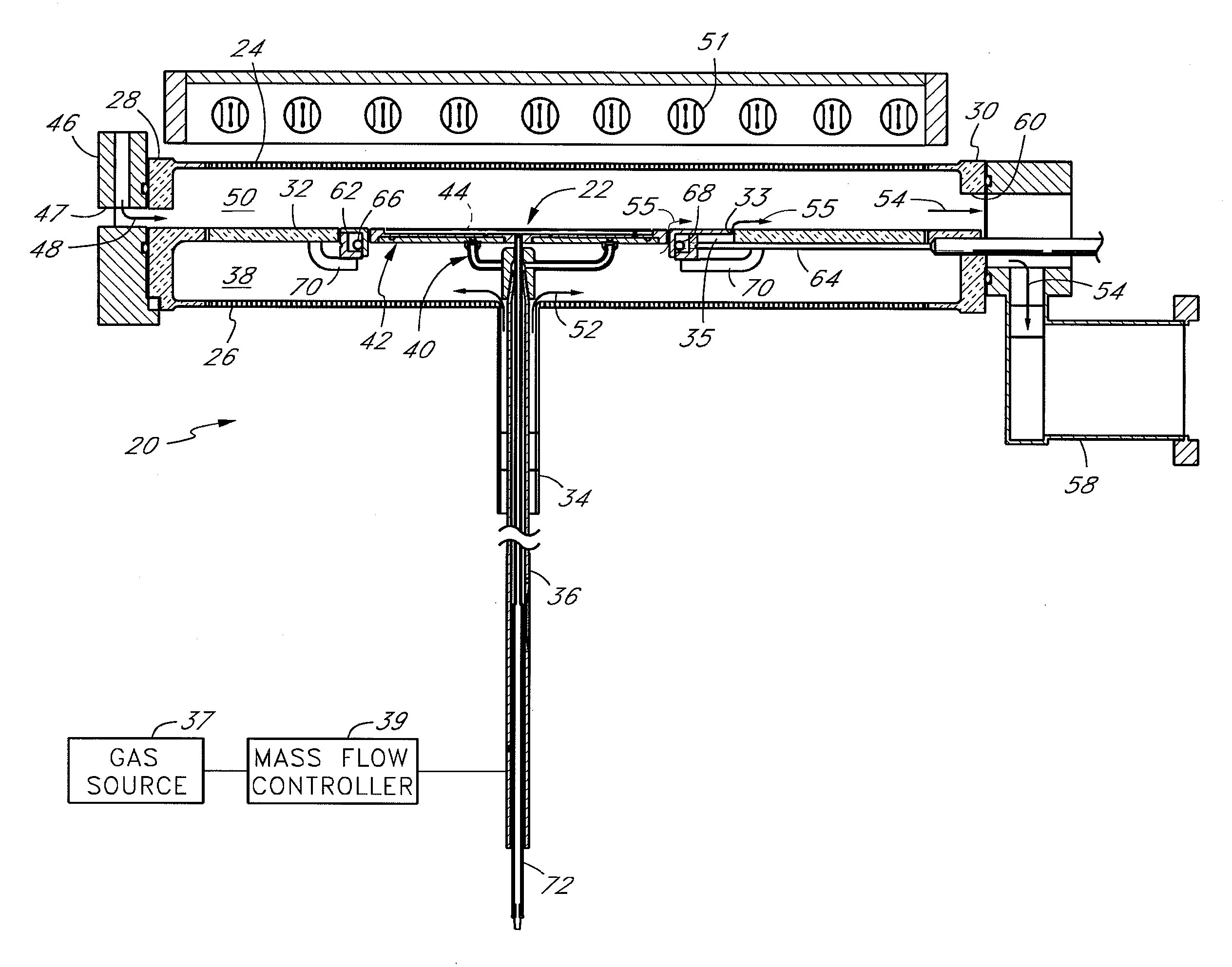
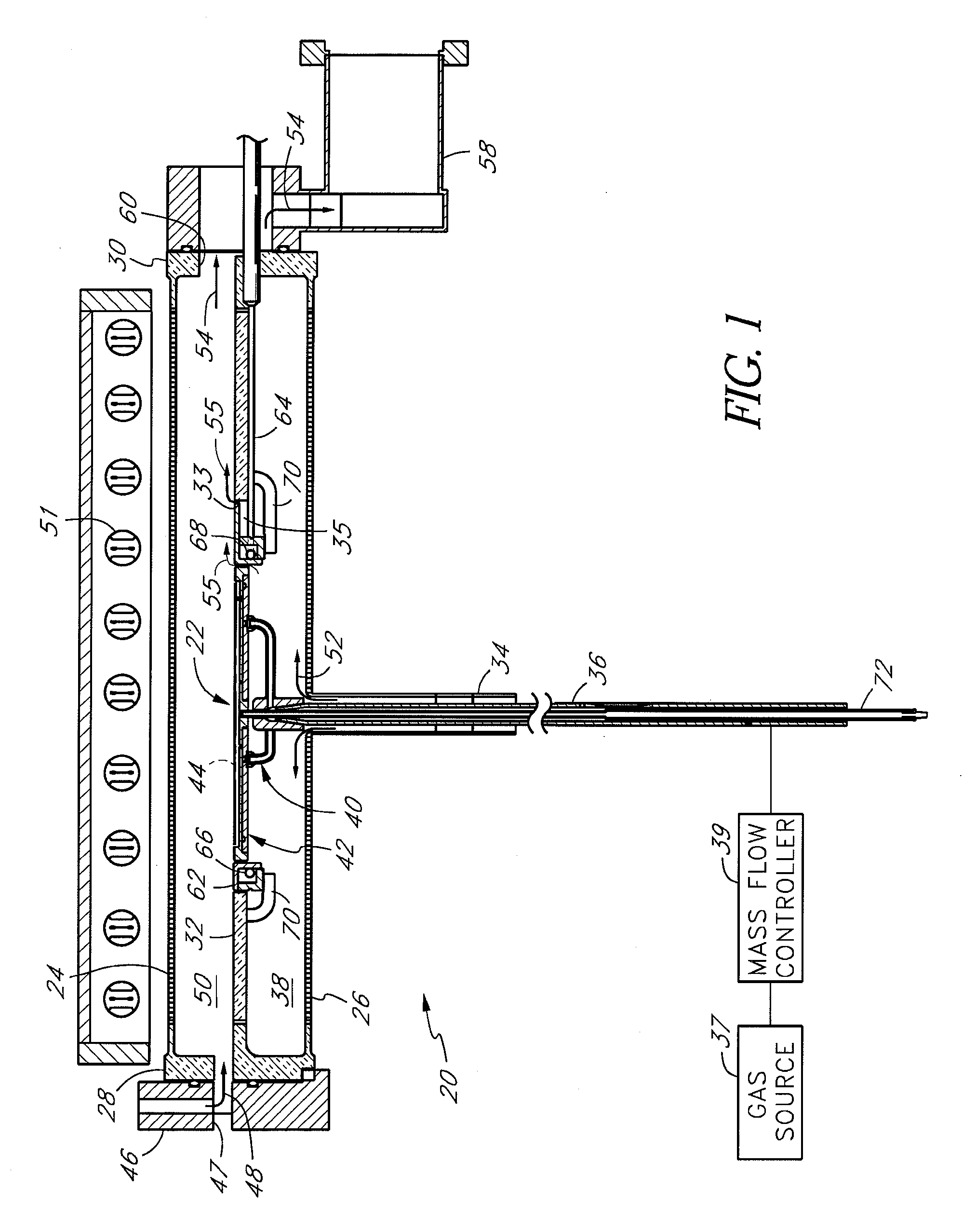
[0036]FIG. 1 illustrates a reactor chamber 20 for processing semiconductor wafers, within which a wafer support system 22 of the present invention is incorporated. Prior to discussing the details of the wafer support system 22, the elements of the reaction chamber 20 will be described. The support system is suitable for many types of wafer processing systems, and the discussion herein should not be limited to one particular type of reaction chamber.

[0037] The chamber 20 comprises a quartz tube defined by an upper wall 24, a lower wall 26, an upstream flange 28, and a downstream flange 30. Although not shown in the figure, the walls have a concave inner surface and a convex outer surface which, when viewed from a lateral cross-section, has a lenticular shape; and lateral edges of the reaction chamber 20 include relatively thick side rails between which a chamber support plate 32 is attached. FIG. 1 is a longitudinal cross-section along a central vertical plane of the chamber 20 illu...


PUM

PropertyMeasurementUnit
temperaturesaaaaaaaaaa
diametersaaaaaaaaaa
thicknessaaaaaaaaaa

Abstract

A wafer support system comprising a susceptor having top and bottom sections and gas flow passages therethrough. One or more spacers projecting from a recess formed in the top section of the susceptor support a wafer in spaced relationship with respect to the recess. A sweep gas is introduced to the bottom section of the susceptor and travels through the gas flow passages to exit in at least one circular array of outlets in the recess and underneath the spaced wafer. The sweep gas travels radially outward between the susceptor and wafer to prevent back-side contamination of the wafer. The gas is delivered through a hollow drive shaft and into a multi-armed susceptor support underneath the susceptor. The support arms conduct the sweep gas from the drive shaft to the gas passages in the susceptor. The gas passages are arranged to heat the sweep gas prior to delivery underneath the wafer. Short purge channels may be provided to deliver some of the sweep gas to regions surrounding the spacers to cause a continuous flow of protective purge gas around the spacers.

Description

RELATED APPLICATIONS [0001] This application is a continuation of application Ser. No. 10 / 642,799, filed Aug. 18, 2003, which is a divisional of copending application Ser. No. 10 / 243,579 filed Sep. 13, 2002, now U.S. Pat. No. 6,692,576, which is a continuation of application Ser. No. 09 / 932,795 filed Aug. 17, 2001, which is a divisional of application Ser. No. 09 / 605,094 filed Jun. 27, 2000, now U.S. Pat. No. 6,343,183, which is a divisional of application Ser. No. 08 / 923,241 filed Sep. 4, 1997, now U.S. Pat. No. 6,113,702, which claims the priority benefit of Provisional application 60 / 039,850 filed Mar. 5, 1997 and is a continuation-in-part of abandoned application Ser. No. 08 / 788,817 filed Jan. 23, 1997, which is a continuation-in-part of application Ser. No. 08 / 706,069 filed Aug. 30, 1996, now U.S. Pat. No. 6,053,982, which claims the priority benefit of Provisional Application No. 60 / 003,132, filed Sep. 1, 1995. This application hereby incorporates by reference herein the entir...

Claims


Application Information

Patent Timeline
Patent Type & Authority Applications(United States)
IPC IPC(8): C23C16/00A21B2/00B24B7/00C23C16/458C23C14/00C23C16/44C23C16/46C23C16/48C23C16/52C23F1/00C30B31/12C30B31/18H01L21/00H01L21/205H01L21/324H01L23/34
CPCC23C16/4586H01L21/68735H01L21/6875H01L21/68792H01L2924/0002H01L2924/00H01L21/68
Inventor HALPIN, MICHAEL W.HAWKINS, MARK R.FOSTER, DERRICK W.VYNE, ROBERT M.WENGERT, JOHN F.VAN DER JEUGD, CORNELIUS A.JACOBS, LOREN R.VAN BILSEN, FRANK B.M.GOODMAN, MATTHEWGLENN, HARTMANNLAYTON, JASON M.
Owner ASM AMERICA INC
Why Eureka
Try Eureka