Optical compensation film, polarizing plate and liquid crystal display apparatus
a liquid crystal display and film technology, applied in the direction of chemistry apparatus and processes, thin material processing, instruments, etc., can solve the problems of inability to achieve performance, difficult to control the orientation along the film thickness direction, and the market of thin-type displays has been upsurging
- Summary
- Abstract
- Description
- Claims
- Application Information
AI Technical Summary
Benefits of technology
Problems solved by technology
Method used
Image
Examples
example 1
(Preparation of DNA / Lipid Complex)
[0080] 5 kg of DNA-sodium salts (average molecular weight of 30,000 bp) derived from salmon sperm (spermatozoon) were dissolved in 5,000 liters of water in a large tank A. 5 kg of n-dodecyltrimethylammonium bromide was dissolved in 500 liters of water in another large tank B. While maintaining the aqueous solutions in the large tanks A and B at 20° C. or less and agitating the aqueous solution in the tank B with an agitation wing, the aqueous DNA solution in the tank A was added to the tank B from the top. The DNA / lipid complex was generated in white precipitate in the tank B, which was then recovered. So as to wash off DNA and lipid remaining in water and never incorporated into the complex, the complex was washed with water as a purification procedure; so as to wash off lipid remaining in the precipitate but never incorporated into the complex, the complex was subjected to a washing procedure with diethyl ether. By thoroughly drying water and di...
example 2
(Preparation of Optical Compensation Film 004 by Solution Filming)
[0084] The same DNA / lipid complex as obtained in Example 1 was dissolved in a solvent methylene chloride / methanol (4 / 1) in a large tank, to obtain a solution of 20% by mass. The solution was fed from the tank through a metal pipe to a die, for use in solution casting on a metal support to make a film. After solvent drying, the film was peeled off from the support and was then transferred; by carrying out longitudinal uniaxial elongation at an effective film elongation of 100% (2.5 as post-elongation length vs. the original length of 1) due to difference in speed between a nip roll on the take-up side and a nip roll on the delivery side while retaining the distance between the nip rolls in front and behind at 0.6 m, the resulting film was transferred, from which the solvent was again dried, to obtain the optical compensation film 004 with a film thickness of 16 μm and properties in Table 1, in a continuous roll form....
example 3
(Preparation of Film 007 by Melt Filming)
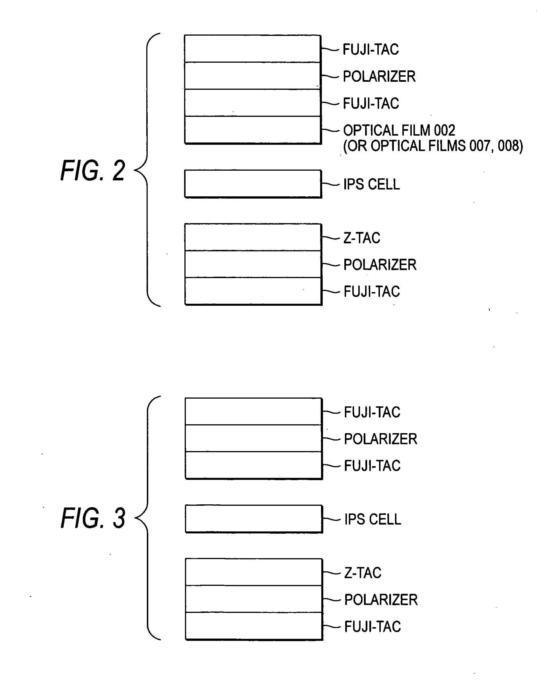
[0087] 20 kg of the powder of the DNA / lipid complex obtained by the same process as in Example 1 was heated and dissolved in a pressure-resistant tank at 150° C., and was fed through a metal pipe to a melt die, for continuous melt filming. In transferring the film, the film was subjected to fixed uniaxial elongation at 150% (2.5 as post-elongation length vs. the original length of 1) along the longitudinal direction in a zone adjusted to a temperature of 110° C. while retaining the width along the crosswise direction with a tenter clip, to obtain an optical compensation film 007 with a film thickness of 40 μm and properties in Table 1, in a continuous roll form.
PUM
 Abstract
Description
Claims
Application Information
 - R&D
- Intellectual Property
- Life Sciences
- Materials
- Tech Scout
- Unparalleled Data Quality
- Higher Quality Content
- 60% Fewer Hallucinations
Browse by: Latest US Patents, China's latest patents, Technical Efficacy Thesaurus, Application Domain, Technology Topic, Popular Technical Reports.
© 2025 PatSnap. All rights reserved.Legal|Privacy policy|Modern Slavery Act Transparency Statement|Sitemap|About US| Contact US: help@patsnap.com


