
VOIP endpoint call admission

a voice and endpoint technology, applied in the field of voice communication over data networks, can solve the problems of user experience a much poorer quality of communication, inability to accept audio synchronization levels, and detrimental to the quality of other calls, and achieve the effect of less expensiv

Inactive Publication Date: 2007-06-14
AVAYA INC
View PDF99 Cites 148 Cited by
  • Summary
  • Abstract
  • Description
  • Claims
  • Application Information

AI Technical Summary

Benefits of technology

[0022] This embodiment decentralizes the call admission control functionality from the switch / media server to the endpoints serviced by the switch / media server. The endpoint and not the switch / media server is best able to evaluate available bandwidth for the requested communication. For example, this embodiment is particularly beneficial for endpoints in virtual private networks where there is a higher likelihood of call failure due to network constraints which are frequently unknown to the switch / server (e.g., the use of a low speed modem link). This embodiment is also particularly beneficial in evaluating available bandwidth between endpoints in different subnets from the switch / media server. The embodiment can reduce significantly network congestion relative to conventional systems by reducing the numbers of calls placed, particularly during periods of high usage.
[0024] The embodiment provides more options to the user to help improve quality for VoIP calls. In a non-mission-critical application, a system that disallows and / or discourages low quality calls may be able to stop overload of a system when the user would exit the call of a certain quality anyway. The thresholds can be configured by network administration and / or by the user himself or herself. User configurable thresholds are particularly attractive as the personal preferences of each user, which vary widely from user to user, can be taken into account by each endpoint. The embodiment can be configured to permit the user to place a call even when the quality will be poor and / or provide detailed reasons for not placing the call, thereby reducing user frustration relative to conventional CAC systems.
[0026] In current phones, such as the Cisco I-Button™ the user is able to view performance metrics, such as latency and packet loss, by pressing a button on the phone. The user, however, must continually press the button to refresh the metrics and determine when call quality is deteriorating, which can be very detracting during the conversation. In contrast, the communication device of this embodiment itself determines automatically when call quality is deteriorating and warns the user accordingly. This permits the user to wrap up the conversation before voice quality deteriorates to a level that is unacceptable.
[0028] This embodiment effectively treats the subscriber communication devices as network probes to provide a real-time, complete, and detailed picture of the bandwidth utilization levels across selected parts of the network. The use of existing devices to perform bandwidth information collection is much less expensive and far simpler than installing a myriad of dedicated network probes at various points in the network.

Problems solved by technology

In VoIP, values for latency, packet loss, and jitter can increase substantially, particularly during periods of heavy network traffic, causing a user to experience a much poorer quality of communication (e.g., audio or video distortion, unacceptable levels of a synchronization between audio and video streams, etc.) than would be experienced if the call were made by a traditional circuit-switched telephony network.
This is particularly true when the network allows any and all calls are allowed to occur, regardless of available bandwidth and the concomitant low quality of the call to be placed and the detrimental impact on the quality of other calls.
First, there is no reason provided to the user regarding the failure to place the call.
This can lead to user frustration and ultimately to a lack of utilization of IP telephony.
Second, it can be very difficult for a call admission controller to determine accurately whether or not to place a call.
For example, if the controller is in a first subnet, a first endpoint is in a second subnet, and a second endpoint is in a third subnet, the controller is often unable to determine whether or not there is sufficient bandwidth available between the second and third subnets for the first and second endpoints to conduct a communication of acceptable quality.
Although the controller can base the decision on pings to the second and third subnets, this is generally not an accurate indicator of available bandwidth.
Third, CAC techniques provide the user with no option about placing the call if predefined criteria are not satisfied.
There are situations when a user may want to place a call even though the call may be of poor quality.

Method used


Image

  • VOIP endpoint call admission
  • VOIP endpoint call admission
  • VOIP endpoint call admission

Examples


Embodiment Construction

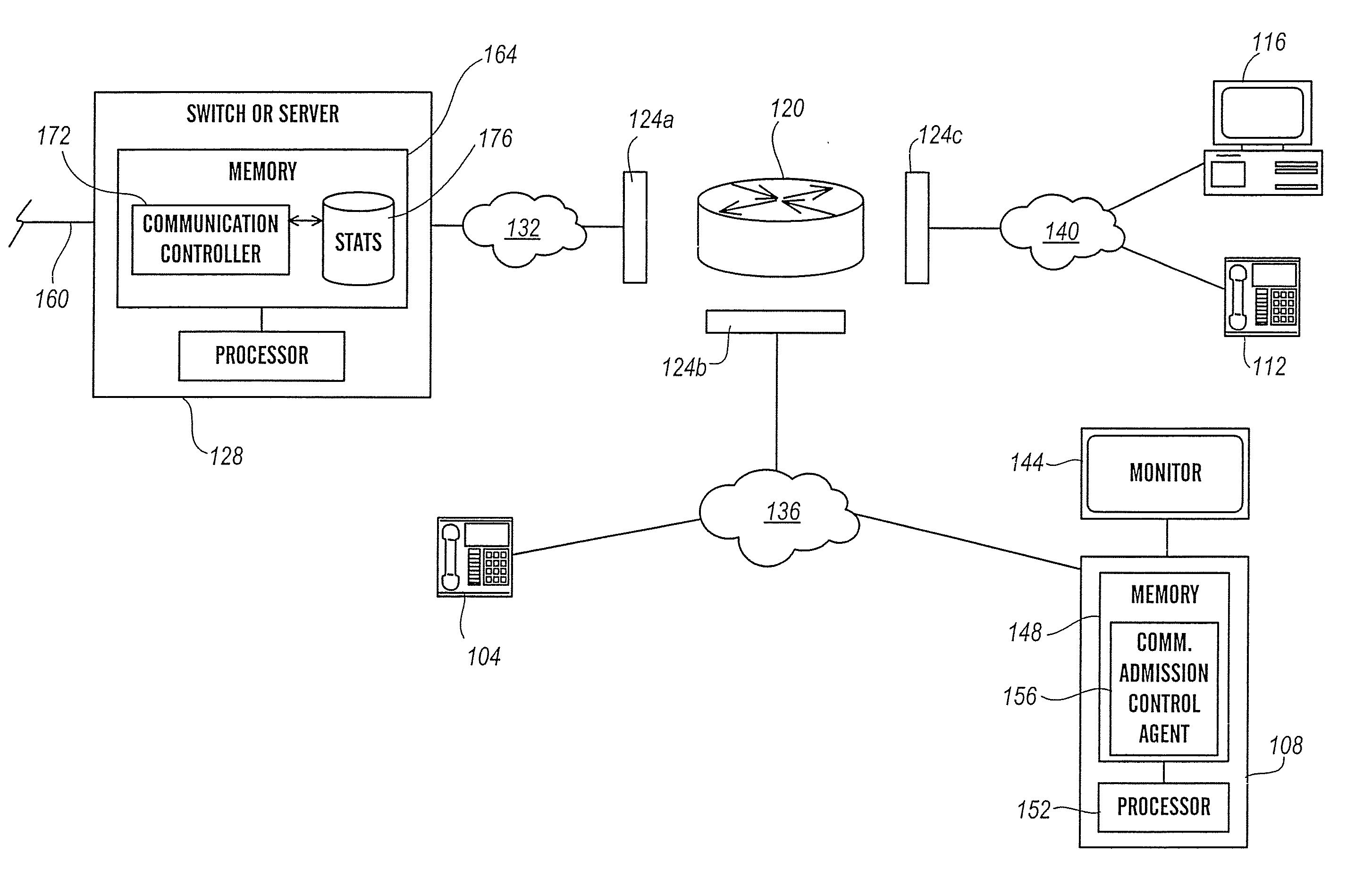
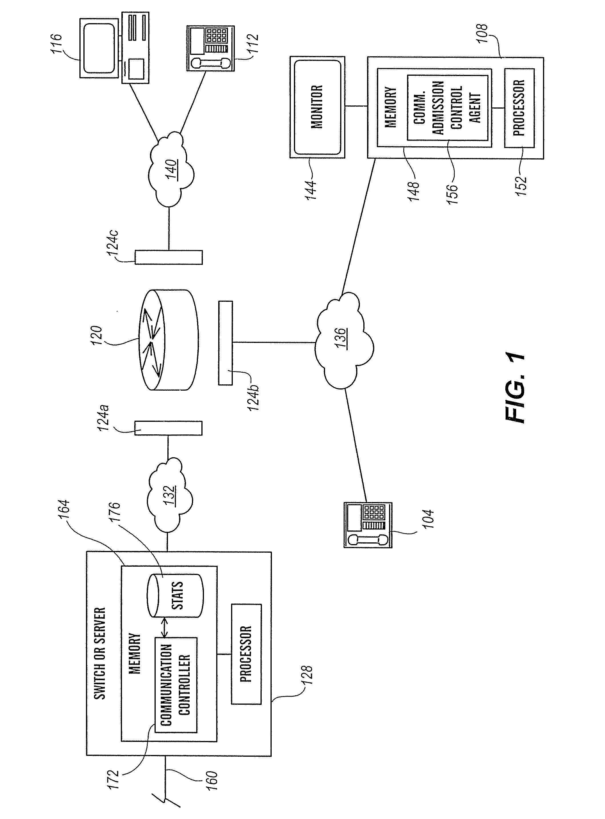
[0036]FIG. 1 depicts a VoIP architecture 100 according to an embodiment of the present invention. The architecture includes a first, second, third, and fourth end points 104, 108, 112, and 116, a router 120 having associated interfaces 124a-c, and switch or server 128. The various components are interconnected by first, second, and third subnets 132, 136, and 140, respectively, which collectively form a local area network. For illustration purposes, the first and third endpoints 104 and 112 are configured as IP hard-phones, while the second and third endpoints 108 and 116 are configured as IP soft-phones. As will be appreciated, the various end points can be any communication device, such as a plain old telephone, a soft phone, an IP hard phone, a personal or laptop computer, a PDA, a pager, and a wireless phone. It is further to be understood that the architecture can include any number of subnetworks and routers, depending on the application, and that the subnets can form a networ...


PUM


Abstract

The present invention is directed generally to an intelligent endpoint or communication device that can collect available bandwidth-related information metrics and / or perform call admission control functions. The present invention is further directed to an architecture comprising a switch or media server in communication with a plurality of subscriber communication devices in which the subscriber communication devices act as network nodes to collect available bandwidth-related information.

Description

CROSS REFERENCE TO RELATED APPLICATIONS [0001] Cross-reference is made to copending U.S. application Ser. No. 10 / 028,874, filed Oct. 22, 2001, to Rankine et al., entitled “Real Time Control Protocol Session Matching”; Ser. No. 10 / 109,784, filed Mar. 29, 2002, to Chavez et al., entitled “Emergency Bandwidth Allocation with an RSVP-Like Protocol”; Ser. No. 10 / 165,719, filed Jun. 7, 2002, to Krumm-Heller et al., entitled “Apparatus and Method for Automatically and Dynamically Reconfiguring Network Provisioning”, and Ser. No. ______, filed concurrently herewith, to Minhazuddin et al., entitled “Instantaneous User Initiation Voice Quality Feedback”, each of which is incorporated herein fully by reference.FIELD OF THE INVENTION [0002] The present invention relates generally to communications over networks and specifically to voice communications over data networks. BACKGROUND OF THE INVENTION [0003] Distributed processing networks are being increasingly used for live voice communications ...

Claims


Application Information

Patent Timeline
IPC IPC(8): H04L12/26H04L12/56H04L12/24H04L29/06
CPCH04L12/2602H04L12/5695H04L29/06H04L29/06027H04L41/046H04L43/00H04L43/0829H04L43/0847H04L43/0852H04L43/0864H04L43/087H04L43/10H04L43/106H04L43/12H04L43/16H04L47/115H04L47/30H04L47/745H04L47/801H04L47/822H04L65/1069H04L47/70H04L9/40H04L65/1101
Inventor HEPWORTH, NEILKRUMM-HELLER, ALEX M.LAVEAU, STEPHANE C.
Owner AVAYA INC
Learn More