Article with intermediate layer and protective layer, and its fabrication

a protective layer and intermediate layer technology, applied in the direction of blade accessories, waterborne vessels, machines/engines, etc., can solve the problems of ceramic thermal barrier coatings subject to failure, limited maximum temperature of environmental coatings, etc., and achieve excellent resistance to oxidation and reduce the tendency of protective layers

Inactive Publication Date: 2005-01-04
GENERAL ELECTRIC CO
View PDF17 Cites 15 Cited by
  • Summary
  • Abstract
  • Description
  • Claims
  • Application Information

AI Technical Summary

Benefits of technology

The present invention provides a protected article and a method for its fabrication. The article is protected by a metallic protective layer that has excellent resistance to oxidation at temperatures above those of conventional metallic protective layers. A structure is provided to reduce the tendency of the protective layer to fail by mechanisms associated with thermal cycling damage as the protected article is heated and cooled over large temperature ranges.
In its most preferred form, the protective layer is a rhodium-based alloy that has excellent oxidation resistance at temperatures as high as 2600° F. However, this protective layer has a much lower coefficient of thermal expansion than that of conventional substrates such as nickel-base superalloys. If the protective layer were applied directly to the substrate, there would be a high likelihood of premature failure of the protected structure as a result of the accumulation of thermal strains and stresses during thermal cycling of the protected article between room temperature and temperatures as high as 2200° F. The interlayer preferably has a coefficient of thermal expansion intermediate between that of the substrate and that of the protective layer to absorb some of the thermal strain and thereby extend the life of the protective structure to greater numbers of thermal cycles in service.

Problems solved by technology

While operable, environmental coatings have maximum-temperature limitations.
Ceramic thermal barrier coatings are subject to failure by impact and thermal cycling damage.

Method used


Image

  • Article with intermediate layer and protective layer, and its fabrication
  • Article with intermediate layer and protective layer, and its fabrication
  • Article with intermediate layer and protective layer, and its fabrication

Examples


Embodiment Construction

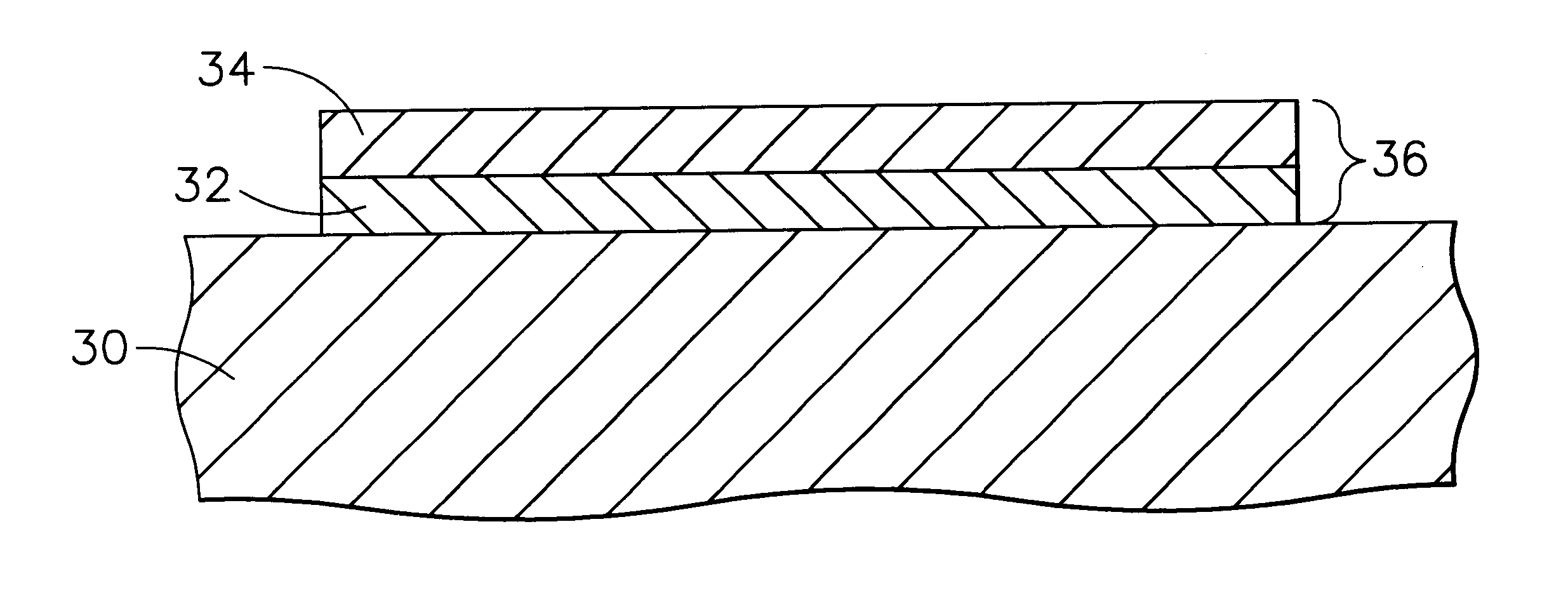
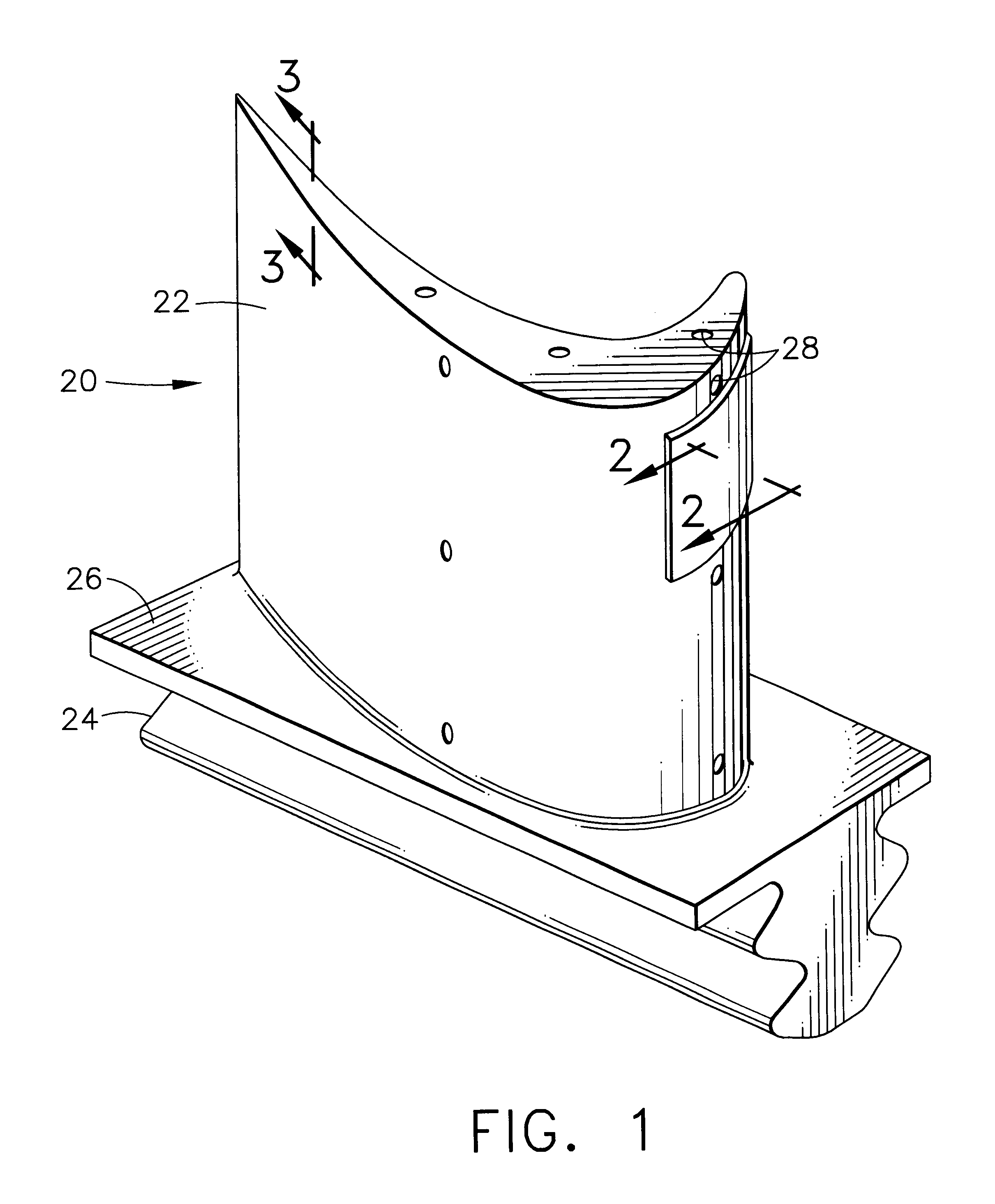
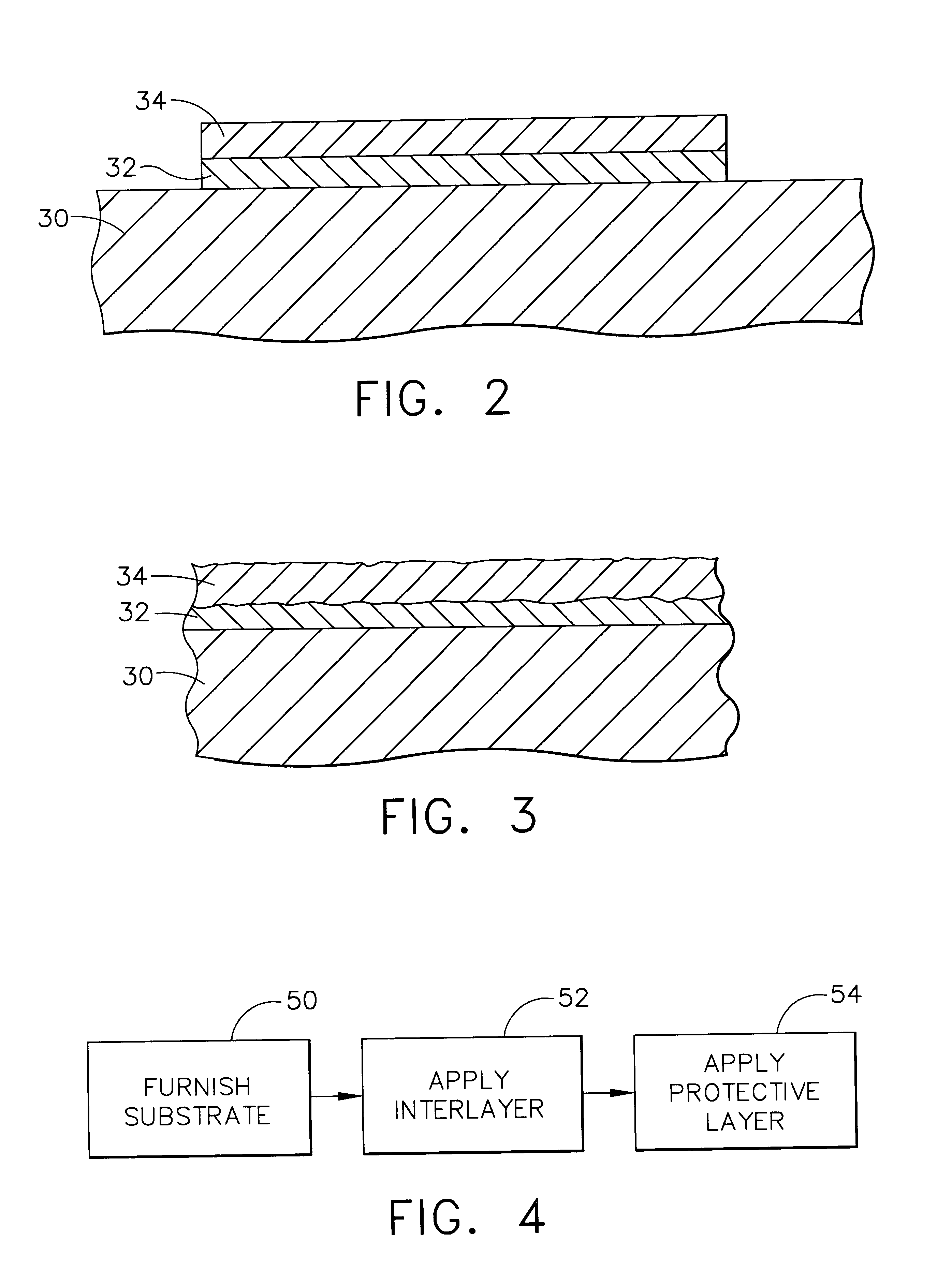
FIG. 1 depicts a component article of a gas turbine engine such as a turbine blade or turbine vane, and in this illustration a turbine blade 20. The turbine blade 20 is formed of any operable material, but is preferably a nickel-base superalloy. The turbine blade 20 includes an airfoil section 22 against which the flow of hot exhaust gas is directed. (The turbine vane has a similar appearance in respect to the pertinent airfoil section, but typically includes other end structure to support the airfoil.) The turbine blade 20 is mounted to a turbine disk (not shown) by a dovetail 24 which extends downwardly from the airfoil 22 and engages a slot on the turbine disk. A platform 26 extends longitudinally outwardly from the area where the airfoil 22 is joined to the dovetail 24. A number of internal passages extend through the interior of the airfoil 22, ending in openings 28 in the surface of the airfoil 22. During service, a flow of cooling air is directed through the internal passages...


PUM

PropertyMeasurementUnit
temperaturesaaaaaaaaaa

Abstract

A protected article includes a nickel-base superalloy substrate, an interlayer overlying the substrate, and a protective layer overlying the interlayer. The protective layer has a composition comprising at least one of rhodium, platinum, palladium, and ruthenium. In one composition, palladium is present in an amount of from about 1 to about 41 atomic percent; platinum is present in an amount of about (40+atomic percent palladium) atomic percent for palladium ranging from about 1 atomic percent to about 14 atomic percent and up to about 54 atomic percent for palladium ranging from about 15 atomic percent up to about 41 atomic percent; rhodium is present in an amount of at least about 24 atomic percent; zirconium, hafnium, titanium, and mixtures thereof are present in an amount of from zero up to about 5 atomic percent; and ruthenium is present in an amount of from zero up to about 5 atomic percent, balance impurities. The interlayer has a coefficient of thermal expansion intermediate between that of the substrate and that of the protective layer. The protected article is fabricated by furnishing the substrate, applying the interlayer over the substrate, and applying the protective layer over the interlayer. The application of the protective layer may be, for example, by welding or attachment of a solid piece.

Description

This invention relates to articles protected by a protective layer and, more particularly, to nickel-base superalloy articles such as gas turbine components protected by a metallic protective layer.BACKGROUND OF THE INVENTIONIn an aircraft gas turbine (jet) engine, air is drawn into the front of the engine, compressed by a shaft-mounted compressor, and mixed with fuel. The mixture is burned, and the hot exhaust gases are passed through a turbine mounted on the same shaft. The flow of combustion gas turns the turbine by impingement against an airfoil section of the turbine blades and vanes, which turns the shaft and provides power to the compressor and fan. In a more complex version of the gas turbine engine, the compressor and a high pressure turbine are mounted on one shaft, and the fan and low pressure turbine are mounted on a separate shaft. In any event, the hot exhaust gases flow from the back of the engine, driving it and the aircraft forwardly.The hotter the combustion gases,...

Claims


Application Information

Patent Timeline
Patent Type & Authority Patents(United States)
IPC IPC(8): B32B15/01C22C27/00C22C5/04C22C5/00C22C27/06
CPCB32B15/018C22C5/04C22C27/06Y10T428/1275Y10T428/12944Y10T428/12868Y10T428/12875Y10T428/12847
Inventor LEE, CHING-PANGJACKSON, MELVIN ROBERTFERRIGNO, STEPHEN JOSEPHTREWILER, GARY EDWARDGORMAN, MARK DANIEL
Owner GENERAL ELECTRIC CO
Why Eureka
Try Eureka