

Fuel injection device for internal combustion engine
- Summary
- Abstract
- Description
- Claims
- Application Information
AI Technical Summary
Benefits of technology
Problems solved by technology
Method used
Image

Examples
Embodiment Construction
[0034] Now, a preferred embodiment of the present invention will be described in detail with reference to the drawings.
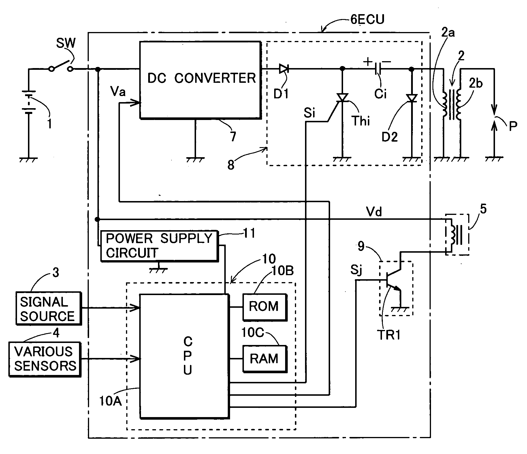
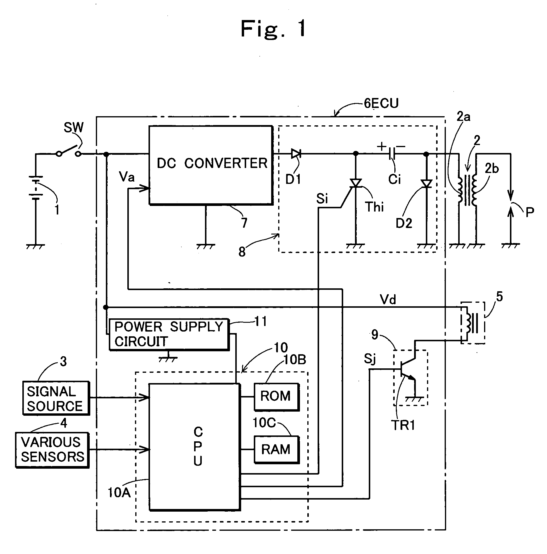
[0035]FIG. 1 shows an exemplary configuration of hardware of a fuel injection device according to the present invention. In FIG. 1, a reference numeral 1 denotes a battery having a grounded negative terminal; 2, an ignition coil; 3, a signal source that generates a pulse signal at a predetermined crank angle position of an engine in synchronization with rotation of the engine; 4, various sensors that detect control conditions required for arithmetically operating fuel injection time; 5, an injector that is mounted to an intake pipe of the engine and injects fuel into the intake pipe downstream of a throttle valve; and 6, an electronic control unit (ECU) that controls an ignition device and a fuel injection device. The sensors 4 include an intake air temperature sensor, a cooling water temperature sensor, an intake pipe internal pressure sensor, a throttle position ...
PUM
 Abstract
Description
Claims
Application Information