Valve for essentially gastight closing a flow path

a vacuum valve and flow path technology, applied in the direction of valve details, valve arrangements, slide valves, etc., can solve the problems of affecting the operation of the vacuum valve, the design of the vacuum valve described is relatively complex, and the gastightness of the flow path cannot always be guaranteed, so as to achieve the effect of simple and compact design, easy maintenance, and withstanding high pressure loads

Active Publication Date: 2007-06-21
VAT HLDG AG
View PDF16 Cites 16 Cited by
  • Summary
  • Abstract
  • Description
  • Claims
  • Application Information

AI Technical Summary

Benefits of technology

[0011] It is therefore an object of the invention to solve the problems described above and to provide a valve of the type mentioned at the outs

Problems solved by technology

Particularly in the case of large pressure variations or change from reduced pressure to excess pressure, or vice versa, a uniform force distribution along the entire circumference of the sealing ring cannot, however, always be ensured.
The design of the vacuum valves described is relatively complex especially owing to the necessity of using a bellows or a plurality of sealing rings for sealing the first disk section from the second disk section and from the valve seat and is disadvantageous to maintain and susceptible to soiling.
Since sealing rings are susceptible a

Method used


Image

  • Valve for essentially gastight closing a flow path
  • Valve for essentially gastight closing a flow path
  • Valve for essentially gastight closing a flow path

Examples


Embodiment Construction

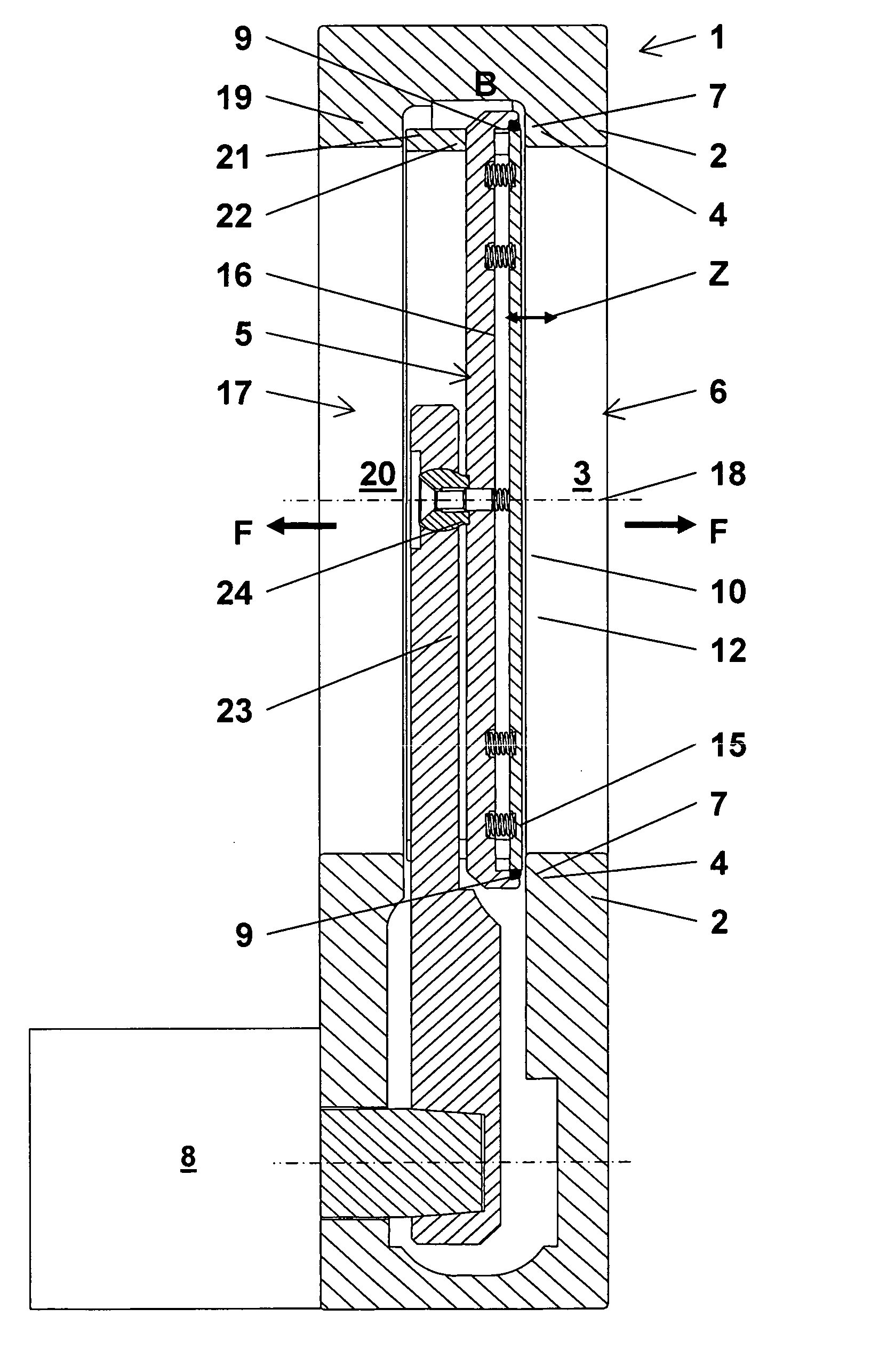
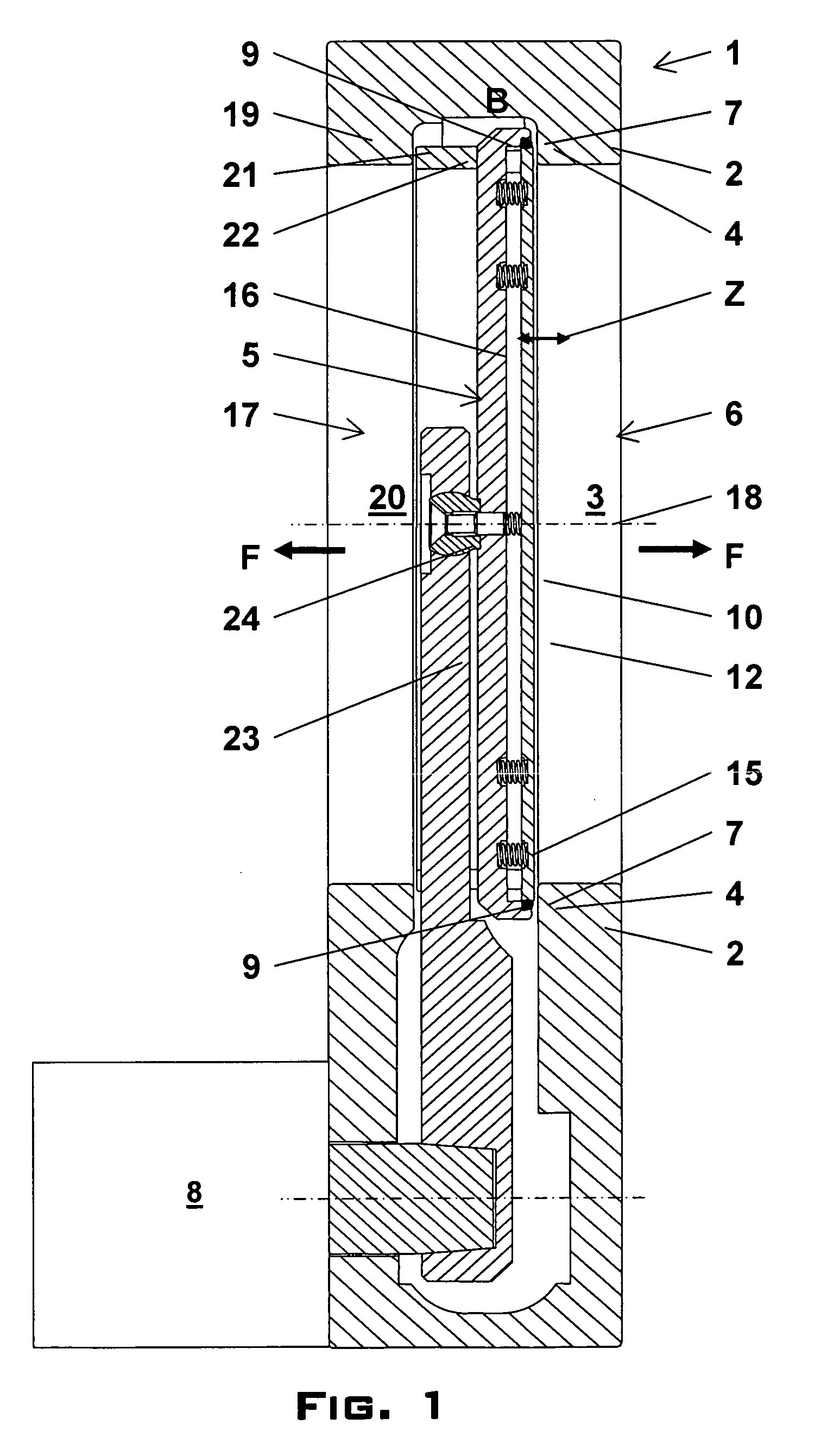
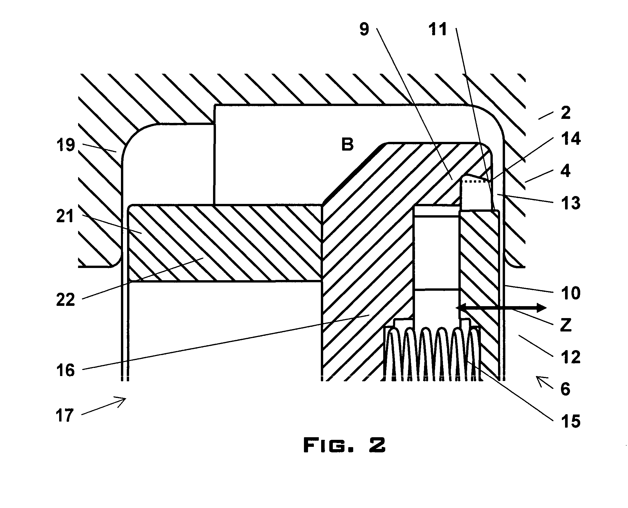
[0037]FIG. 1 shows a possible embodiment of the valve according to the invention in the form of a shuttle valve. In a valve housing 1 having two walls opposite one another a distance apart, a first wall 2 and a second wall 19, two openings likewise opposite one another and having a round cross-section, a first opening 3 and a second opening 20, are formed, which openings form a flow path F leading through the valve for a gas or fluid. The two openings 3 and 20 have a common opening axis, the central axis 18 of the first opening 3. A first valve seat 4 which surrounds the first opening 3 and is formed by a flat, defined area of the first wall 2 and through whose plane the central axis 18 passes perpendicularly is formed on the inner areas of the first wall 2. Also present on the inner area of the second wall 19, parallel to the first valve seat 4, is a second valve seat 21. A drive 8 which is connected by means of an arm 23 to a valve disk 5 is arranged on the valve housing 1. The va...


PUM


Abstract

The invention relates to a valve, in particular a shuttle or sliding valve, for essentially gastight closing of a flow path (F). The valve includes a valve housing (1;1a) having a first wall (2) which has a first opening (3) and a first valve seat (4), a valve disk (5) having a closing side (6) with a sealing ring (7) and at least one drive (8). Through the drive (8), the valve disk (5) is pivotable or displaceable from an opened position (A) essentially parallel to the first valve seat (4), and the perpendicular distance between the valve disk (5), and the first valve seat (4) can be reduced so that, in the closed position (C), the flow path (F) is closed essentially gastight by an axially sealing contact between the sealing ring (7) and the first valve seat (4). The valve disk (5) includes an outer disk section (9), which is connected to the drive (8) and fixes the sealing ring (7) in the perpendicular direction to the first valve seat (4), and an inner disk section (10) which has an outer circumferential area (11) and which is mounted so as to be movable relative to the outer disk section (9) in a direction (Z) essentially perpendicular to the first valve seat (4). The outer circumferential area (11) is enclosed essentially gastight with an inner seal by the sealing ring (7). Thus, in the closed position (C), a pressure difference at the valve disk (5) acts essentially on the inner disk section (10) so that the inner disk section (10), decoupled from the outer disk section (9), is supported perpendicularly on a section of the valve housing (1), in particular the first valve seat (4) or a lateral groove (27).

Description

TECHNICAL FIELD OF THE INVENTION [0001] The invention relates to a vacuum valve for essentially gastight closing of a flow path by swivelling or moving a valve disk over an opening and pressing the valve disk onto a valve seat surrounding the opening. Such valves are used in particular in vacuum technology and are referred to in particular as shuttle valves or sliding valves. DESCRIPTION OF THE PRIOR ART [0002] Valves of the type mentioned at the outset are known in different embodiments from the prior art and are used in particular in the area of IC and semiconductor manufacture, which must take place in a protected atmosphere, as far as possible without the presence of contaminating particles. Shuttle valves serve, for example, for controlling the gas flow between a process chamber and a vacuum pump. Sliding valves are arranged, for example, in connecting passages between manufacturing chambers of a manufacturing plant for semiconductor wafers or liquid crystal substrates, it bein...

Claims


Application Information

Patent Timeline
IPC IPC(8): F16K1/16
CPCF16K3/10F16K51/02F16K3/04F16K3/02F16K25/00
Inventor GEISER, FRIEDRICH
Owner VAT HLDG AG
Why Eureka
Try Eureka