
Dielectric barrier discharge lamp drive circuit

Inactive Publication Date: 2007-06-21
SANYO ELECTRIC WORKS LTD
View PDF1 Cites 4 Cited by
  • Summary
  • Abstract
  • Description
  • Claims
  • Application Information

AI Technical Summary

Benefits of technology

[0011] It is an object of the present invention to provide a dielectric barrier discharge lamp drive circuit driven by relatively low voltage and having a small power loss with a simple configuration, that is, without using reinforcement members in the dielectric sealed container even when the dielectric barrier discharge lamp has a relatively large area and includes a dielectric container having a thickness for sufficient strength.
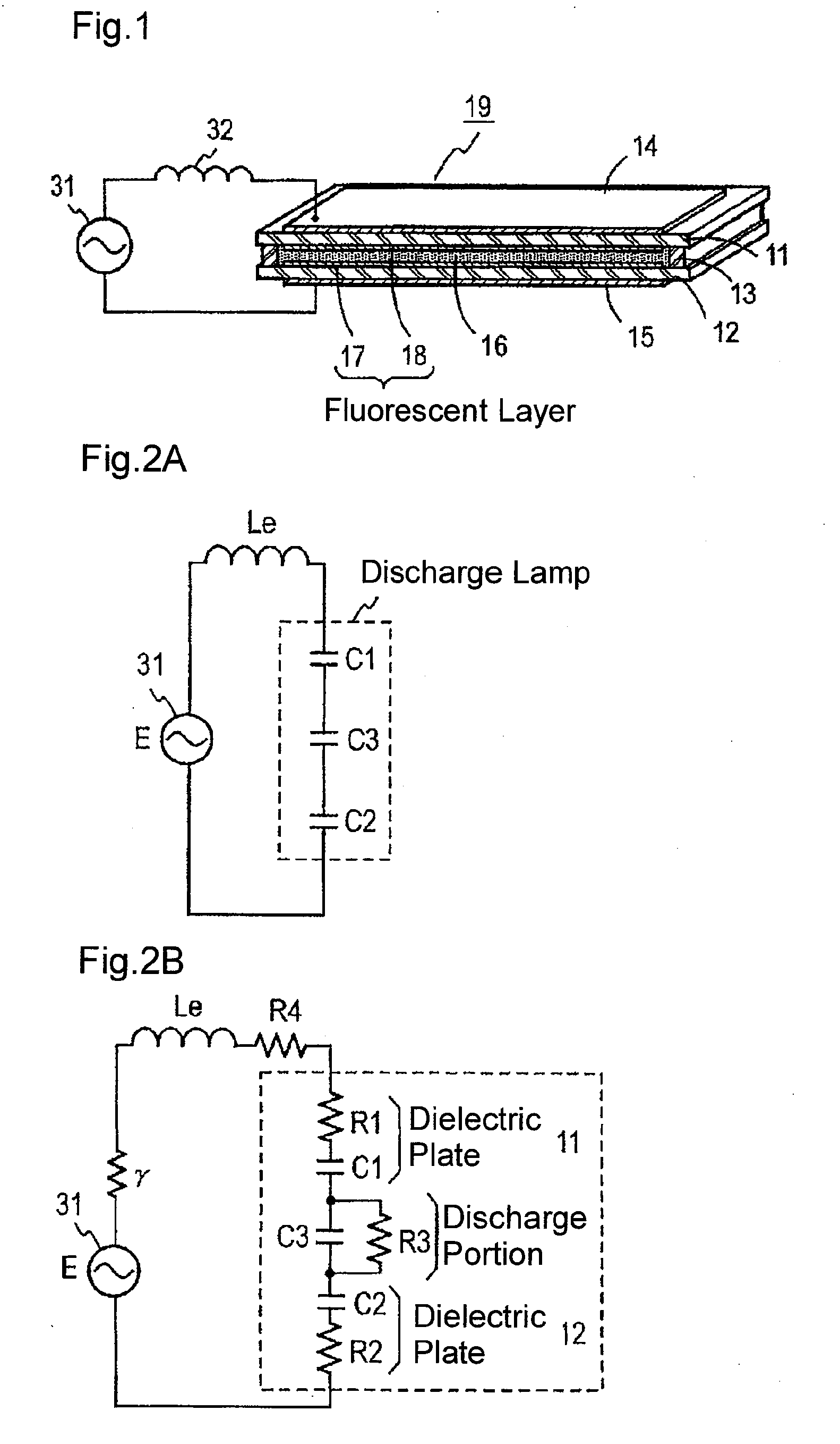
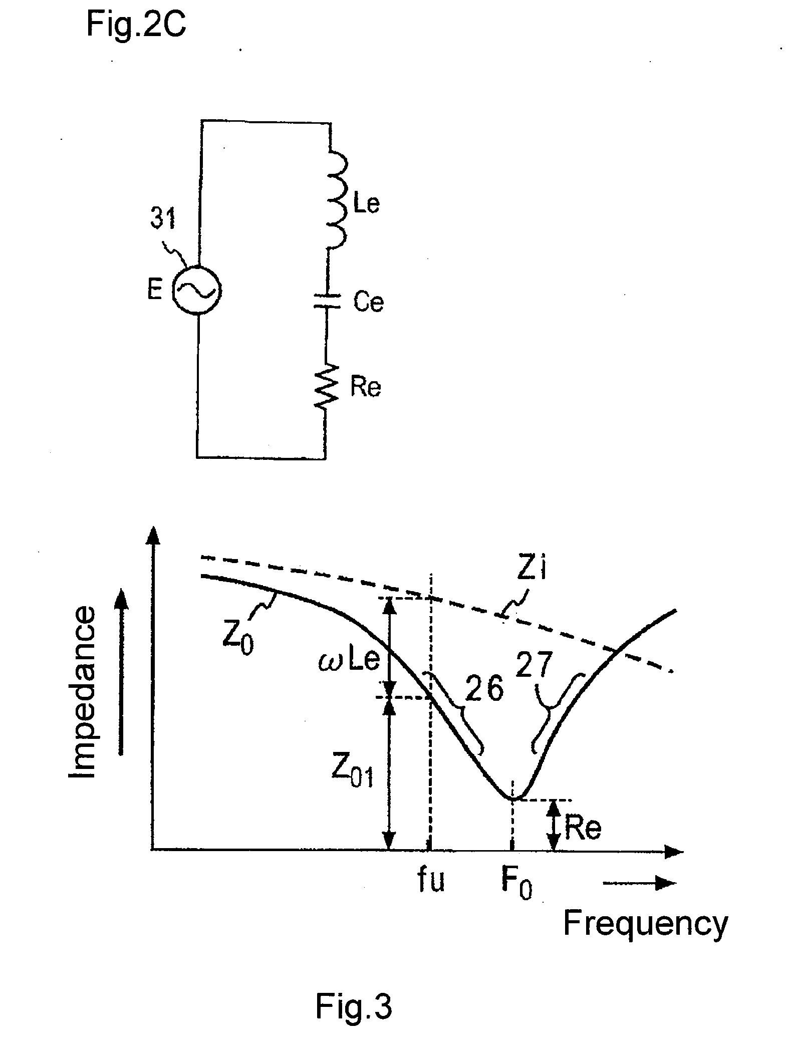
[0013] In the present invention, the impedance of the dielectric barrier discharge lamp when viewed from the drive circuit corresponds to a reduced impedance of a dielectric electrostatic capacitor forming discharge space with the impedance of a reactor component member. The reduced impedance enables the drive voltage to be decreased. Thus, a dielectric body having a thickness for solely obtaining sufficient mechanical strength may be used. Further, the power factor is improved and loss is reduced. Additionally, there is no need for the structure of the discharge lamp to be complicated, and the size and weight may be reduced with a light emission surface having a relatively large area. The dielectric body forming the discharge space may be planar and formed by two flat plates or may be cylindrical and formed by two curved plates.

Problems solved by technology

Thus, equipment used as the flat panel discharge lamp lighting device becomes extremely large and it becomes difficult to make the equipment thinner or lighter.
However, when used in the field of illumination in which a relatively large area is required, the arrangement of a plurality of ribs as reinforcement members will affect the uniformity of light emission in an undesirable manner.
Further, the manufacturing steps would increase thereby raising costs.

Method used


Image

  • Dielectric barrier discharge lamp drive circuit
  • Dielectric barrier discharge lamp drive circuit
  • Dielectric barrier discharge lamp drive circuit

Examples


first embodiment

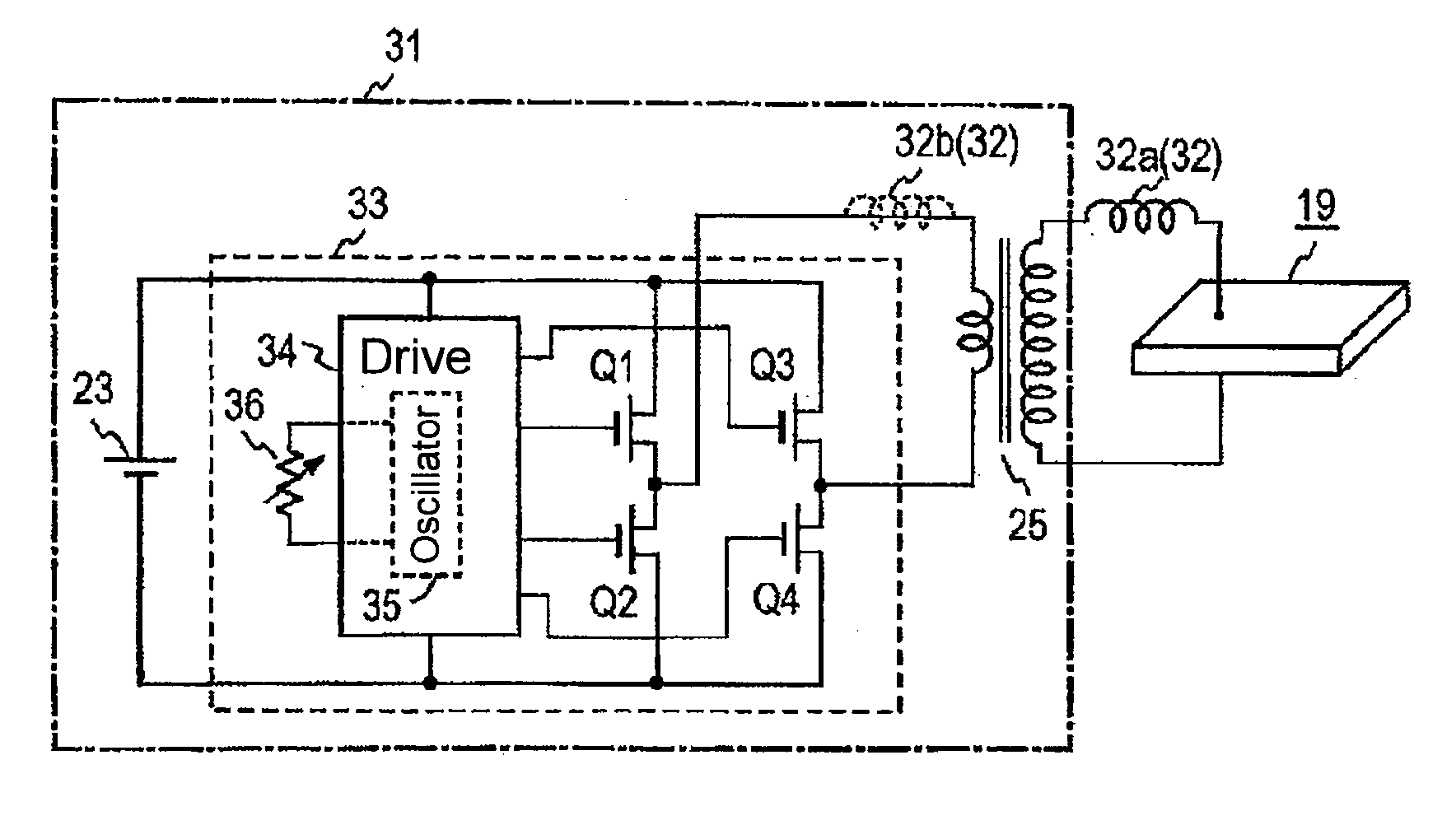
[0038] A dielectric barrier discharge lamp drive circuit according to a first embodiment of the present invention will now be described with reference to FIG. 4. The DC power from a DC power supply 23 is converted to high frequency power by an inverter 33 in a drive AC generation circuit 31. The high frequency power is boosted from about 12 V to about 1 kV to 2 kV by a step-up transformer 25. The boosted high frequency power is then applied to the flat panel discharge lamp 19 via an inductance element 32a, which functions as the reactor member 32. The DC power supply 23 may be configured, for example, so that the DC power is generated by rectifying commercial AC power, as shown in FIG. 8.

[0039] The inverter 33 may have a configuration similar to that of the prior art. As shown in FIG. 4, a series-connected circuit of switching elements Q1 and Q2 and a series-connected circuit of switching elements Q3 and Q4 are connected to the DC power supply 23. A primary coil of the transformer ...

second embodiment

[0045] A dielectric barrier discharge lamp drive circuit according to a second embodiment of the present invention will now be described with reference to FIG. 5. In the second embodiment, the high frequency AC power from the AC power generation circuit 31 is applied to the flat panel discharge lamp 19 via a leakage transformer 37, which functions as the reactor member 32. In the example shown in FIG. 5, the leakage transformer 37 is connected to the output of the inverter 33 in place of the transformer 25 of FIG. 4, and a flat panel discharge lamp 19 is directly connected to the leakage transformer 37. For example, a neon transformer used to light the neon lamp is used to prevent overcurrent in a lighted state. However, the leakage transformer is not used as the transformer 25 as shown in FIG. 8 since the dielectric barrier discharge lamp itself has the current limiting function, as described above. The second embodiment is configured so that the reactance component of the leakage ...


PUM


Abstract

A dielectric barrier discharge lamp drive circuit having a thickness so that sufficient mechanical strength of a glass plate is obtained and a relatively large illumination area. The drive circuit is driven at low voltage and reduces apparent current. The drive circuit applies a high frequency power to a flat panel discharge lamp (19) with a reactor (32). In a lighted state, a state close to a series resonance of the inductance of the reactor and an electrostatic capacity of the glass plate (11, 12) is set. The inductance value of the reactor is selected so that the frequency of the high frequency power is slightly smaller than the series resonance frequency, and the impedance of the load as viewed from an AC source (31) is set to the rated impedance. A high light emitting efficiency is obtained in such a configuration when Xe (xenon) gas that does not cause environmental problems is used as the discharge gas.

Description

TECHNICAL FIELD [0001] The present invention relates to a discharge lamp, and more specifically, to a drive circuit for lighting a so-called dielectric barrier discharge lamp provided with a current limiting function for preventing impedance of the discharge lamp itself from causing overcurrent when emitting light through discharge. BACKGROUND ART [0002] Known dielectric barrier discharge lamps have a planar or cylindrical shape. As shown in FIG. 8, a flat panel discharge lamp (refer to, for example, patent publication 1) has dielectric plates 11 and 12, which resemble glass plates and which are arranged facing each other. The space between the edges of the opposing surfaces of the dielectric plates 11 and 12 are sealed by a sealing member (e.g., seal glass) 13 so as to form a dielectric sealed container. Discharge gas 16 is contained in the dielectric sealed container, and electrodes 14 and 15 are attached facing each other with the dielectric plates 11 and 12 and the discharge gas...

Claims


Application Information

Patent Timeline
IPC IPC(8): H05B37/02H01J65/04H05B41/24H05B41/28
CPCH01J65/046H05B41/24H05B41/2806Y02B20/22Y02B20/00
Inventor NODA, MAKOTO
Owner SANYO ELECTRIC WORKS LTD
Learn More