Device and method for controlling output of rechargeable battery
a rechargeable battery and output technology, applied in the direction of engine-driven generators, electric devices, machines/engines, etc., can solve the problems of polarity inversion, hev may not be able to start the engine, and the tendency to polarity inversion to occur, so as to suppress the shortening of the life of the rechargeable battery
- Summary
- Abstract
- Description
- Claims
- Application Information
AI Technical Summary
Benefits of technology
Problems solved by technology
Method used
Image

Examples
first embodiment
[0035] The controller 1 for the rechargeable battery 40 and a method for controlling the output of the rechargeable battery 40 according to the present invention will now be described with reference to FIGS. 1 to 5.
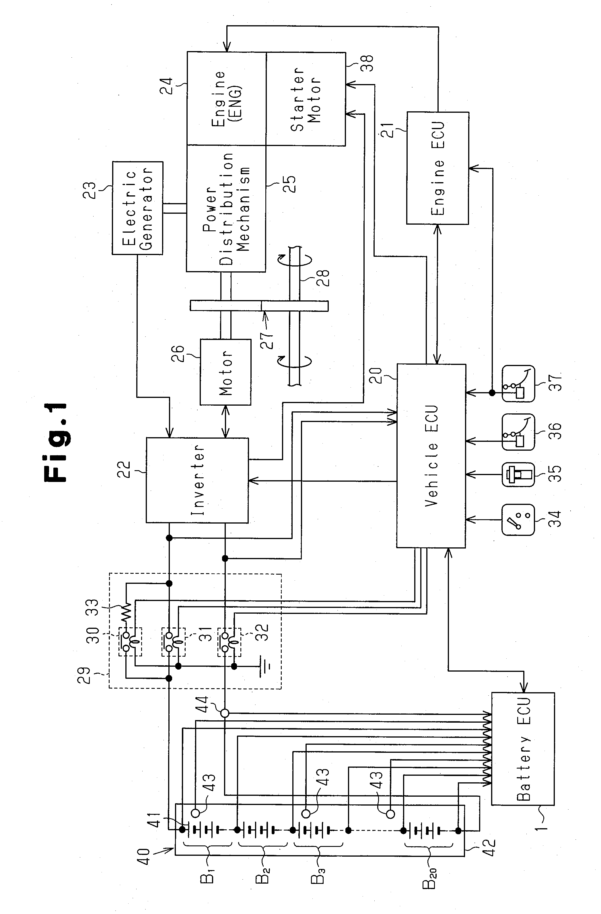
[0036]FIG. 1 is a schematic block diagram showing an electrical configuration of a vehicle including a controller 1 for the rechargeable battery 40.
[0037] As shown in FIG. 1, the vehicle including the controller 1 for the rechargeable battery 40 is an HEV. The vehicle includes an internal combustion engine 24 and a motor 26, which function as a power source for transmitting power to a drive shaft 28. The drive shaft 28 is connected to vehicle wheels (not shown). When the vehicle is motor-driven, the rechargeable battery 40 functions as a power supply source for the motor 26.
[0038] The rechargeable battery 40 supplies power to the motor 26 via a relay unit 29 and an inverter 22. The rechargeable battery 40 also supplies power to a starter motor 38 for starting the engine...
second embodiment
[0092] the present invention will now be described with reference to FIGS. 6 to 8.
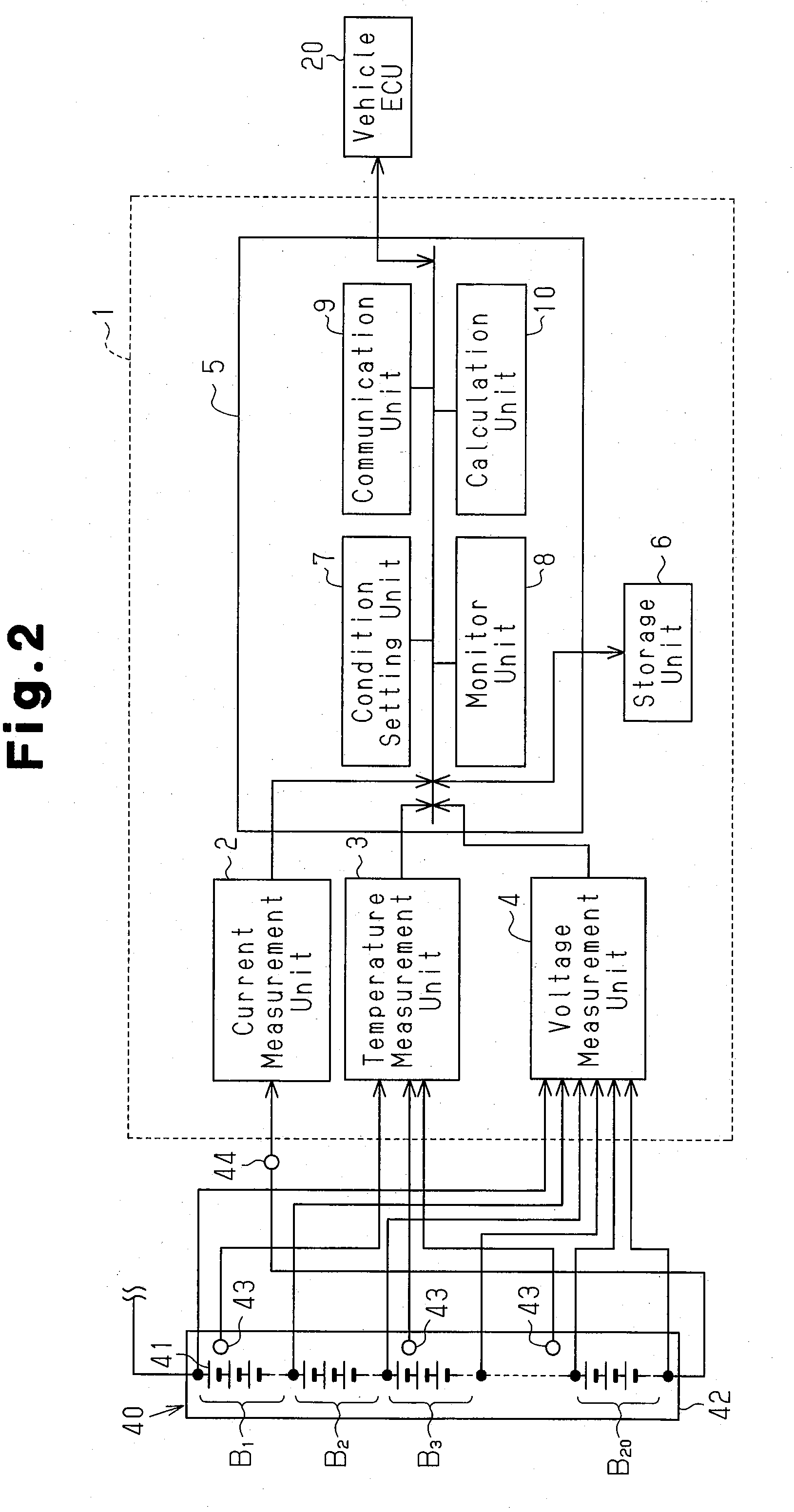
[0093] The rechargeable battery subject to control in the second embodiment is similar to the rechargeable battery 40 of the first embodiment shown in FIGS. 1 and 2. The controller for the rechargeable battery of the second embodiment, which is similar to the controller 1 for the rechargeable battery 40 of the first embodiment shown in FIGS. 1 and 2, is mounted on the HEV. To avoid redundancy, like or same reference numerals are given to those components that are the same as the corresponding components of the first embodiment.
[0094]FIG. 6 is a graph showing changes in the SOC of the rechargeable battery 40 when the upper limit value is lowered by the monitor unit 8 of the second embodiment. FIG. 7 is a graph showing changes in the SOC of the rechargeable battery 40 with respect to the short term discharge stop SOC when the upper limit value is lowered by the monitor unit 8 of the second embodiment in...
third embodiment
[0114] the present invention will now be described with reference to FIG. 9.
[0115] The rechargeable battery subject to control in the third embodiment has the same configuration as the rechargeable battery 40 of the first embodiment shown in FIGS. 1 and 2. The controller for the rechargeable battery of the third embodiment, which is similar to the controller 1 for the rechargeable battery 40 of the first embodiment shown in FIGS. 1 and 2, is mounted on an HEV. To avoid redundancy, like or same reference numerals are given to those components that are the same as the corresponding components of the first embodiment.
[0116] In the third embodiment, the terminal voltage (block voltage) of the rechargeable battery 40 and the SOC of the rechargeable battery 40 are both used as indexes indicating the charged state of the rechargeable battery 40. The discharge is suspended when the terminal voltage and the SOC of the rechargeable battery 40 are both lowered to a predetermined value.
[0117]...
PUM
 Abstract
Description
Claims
Application Information
 - R&D
- Intellectual Property
- Life Sciences
- Materials
- Tech Scout
- Unparalleled Data Quality
- Higher Quality Content
- 60% Fewer Hallucinations
Browse by: Latest US Patents, China's latest patents, Technical Efficacy Thesaurus, Application Domain, Technology Topic, Popular Technical Reports.
© 2025 PatSnap. All rights reserved.Legal|Privacy policy|Modern Slavery Act Transparency Statement|Sitemap|About US| Contact US: help@patsnap.com