
Blowing agent introduction systems and methods

a technology of blowing agent and introduction system, which is applied in the field of polymer foam processing, can solve the problems of discontinuous processing techniques such as injection molding and blow molding, lack of control, and uneven distribution of blowing agent in the polymer material

Inactive Publication Date: 2007-06-21
TREXEL
View PDF68 Cites 41 Cited by
  • Summary
  • Abstract
  • Description
  • Claims
  • Application Information

AI Technical Summary

Benefits of technology

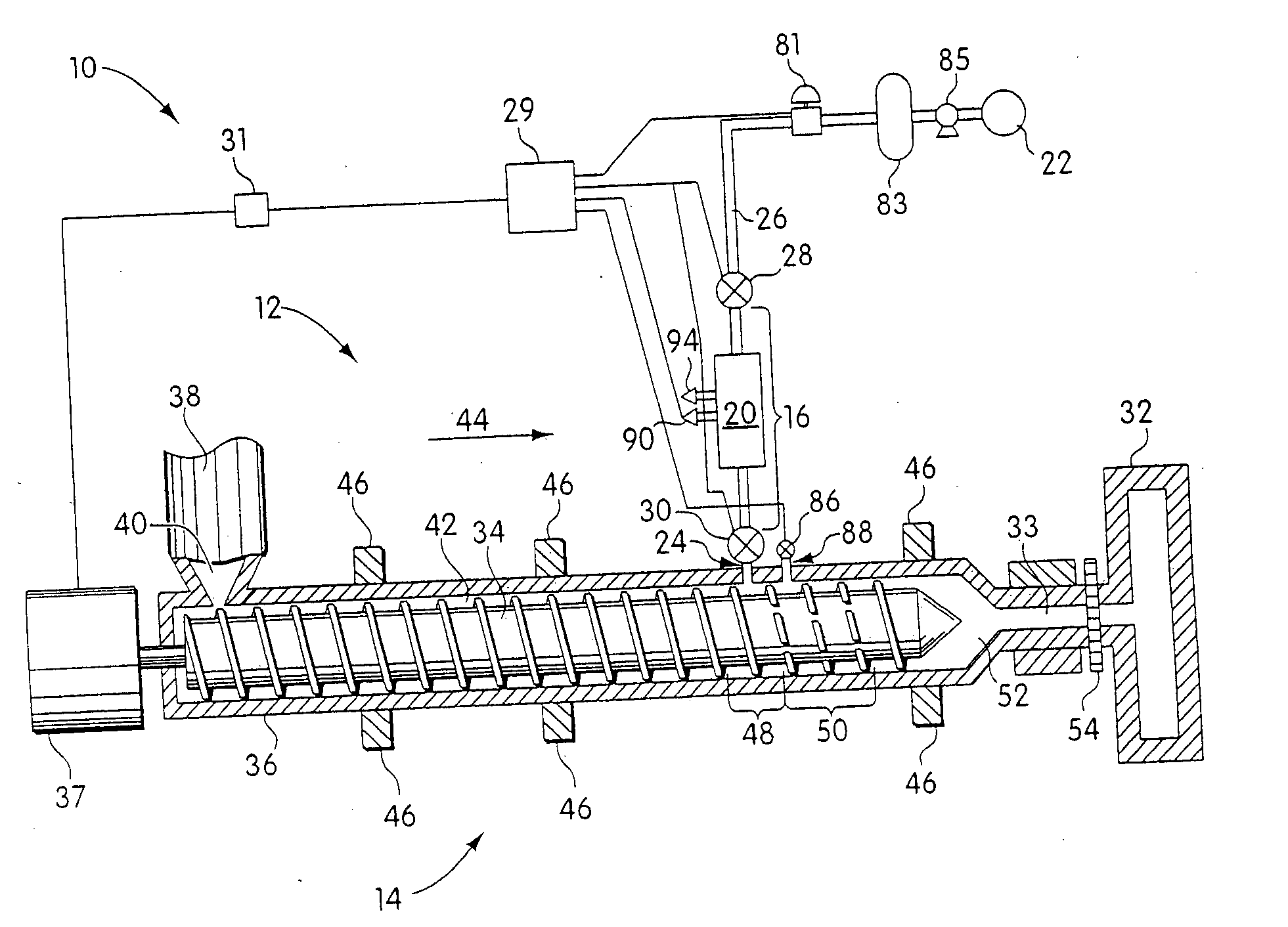
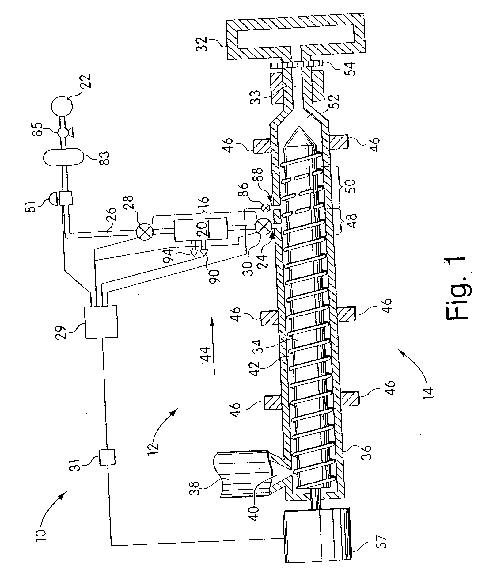
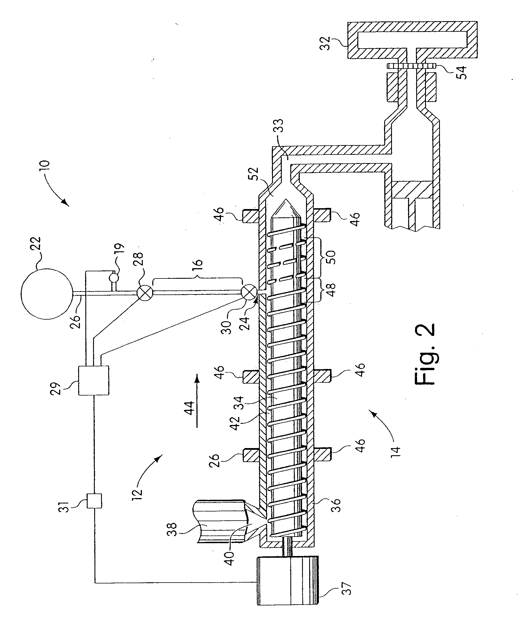
"The invention provides a system for introducing blowing agent into a polymeric foam processing system. The system includes an accumulator, a pressure regulating device, and a control system. The accumulator has an inlet for receiving the blowing agent and an outlet for connecting to the extruder. The control system receives a signal from a pressure measuring device in the extruder and adjusts the pressure of the blowing agent in the accumulator to control the pressure of the blowing agent in the extruder. This system allows for precise control of the pressure of the blowing agent and ensures a consistent and safe processing of polymeric foam."

Problems solved by technology

Some processing techniques, such as injection molding and blow molding, may be discontinuous.
In discontinuous processes, including certain injection molding and blow molding processes, such continuous introduction systems may cause a lack of control over the percentage of blowing agent injected into the polymeric material and may lead to an uneven distribution of the blowing agent in the polymeric material.
The uneven distribution of blowing agent may result in viscosity variations within the polymeric material in the extruder which can cause output inconsistencies and other problems.
Such effects may generally reduce control over the process and may narrow the processing window.
However, in other processes, such as discontinuous processes that require relatively precise control over blowing agent introduction, the conventional introduction systems may impair the process for one or more of the reasons described above.
In particular, certain processes for producing small molded articles and / or microcellular foam articles may be adversely affected if the blowing agent is not precisely controlled.

Method used


Image

  • Blowing agent introduction systems and methods
  • Blowing agent introduction systems and methods
  • Blowing agent introduction systems and methods

Examples


example 1

[0085] The example illustrates the use of one embodiment of the invention.

[0086] The injection molding machine used was a 55-ton machine having a 20 mm screw. A blowing agent introduction system was connected to the injection molding machine. The blowing agent introduction system included an inlet valve, an outlet valve which was incorporated into a blowing agent injector assembly, and a specific length of conduit to establish the accumulator volume in which the charge or dose of the blowing agent was accumulated prior to introduction into the polymer melt, as described below. The pressure supplied to the accumulator volume was monitored and controlled using a back-pressure regulator on a T-shaped portion of the conduit with an outlet vented to air. The temperature of the tubing was measured using a handheld surface thermocouple device.

[0087] The accumulator volume was calculated as the sum of the injector assembly volume, the inlet valve volume downstream of the shut-off valve se...

example 2

[0093] This is an example of an embodiment of the invention using a lower dosing rate of blowing agent.

[0094] Process parameters in the apparatus in this example were the same as that of Example 1, but the nitrogen pressure in the accumulator volume was set to 2475 psi with a polymer melt pressure of 2350 psi. The calculated amount of nitrogen delivered was approximately 3.8 mg, and the temperature was about 250° F. The system parameters were not changed during the run, and the parts were consistently produced for approximately two hours.

example 3

[0095] The example illustrates the use of another embodiment of the invention. In particular, this example illustrates the use of the blowing agent introduction system in connection with a process where the total part weight required a small percentage of the stroke of the machine. In this example, the stroke required was about 7% of the total machine capacity. Typical blowing agent introduction systems cannot be easily operated with consistency at less than 15% of the machine stroke capacity.

[0096] The injection molding machine used was a 88-ton machine having a 30 mm screw. The injection molding machine was connected to the blowing agent injection assembly described in Example 1.

[0097] The mold in the injection-molding machine was used to produce a U-shaped part having a solid part weight of 6.5 g. The mold had two cavities which were connected by a centered, cold sprue. The material used was a glass-filled Nylon 6.

[0098] Using an equation for the density of nitrogen as a funct...


PUM

PropertyMeasurementUnit
pressureaaaaaaaaaa
volumeaaaaaaaaaa
pressureaaaaaaaaaa

Abstract

The present invention provides blowing agent introduction systems and methods for introducing blowing agent into polymeric foam processing systems. The methods may involve introducing one or more doses of blowing agent into polymeric material in an extruder during a plastication period of a molding cycle. Prior to introduction, a dose is confined in an accumulator which, for example, has a volume defined between an inlet valve and an outlet valve. A control system may receive inputs related to system parameters (e.g., pressure of polymeric material in extruder, axial position of screw in barrel, whether screw is rotating, and the like) and based on the inputs coordinates operation of the valves to confine and introduce the blowing agent dose(s). The introduction systems may be used in discontinuous plasticating processes, such as injection molding and blow molding, and can be particularly useful in processes that use precise quantities of blowing agent.

Description

RELATED APPLICATIONS [0001] This application is a divisional of U.S. patent application Ser. No. 10 / 281,891, filed on Oct. 28, 2002 which is incorporated herein by reference.BACKGROUND [0002] 1. Field of the Invention [0003] The present invention relates generally to polymer foam processing and, more particularly, to systems and methods for introducing blowing agent into polymeric material in a polymeric foam process. [0004] 2. Description of the Related Art [0005] Polymeric materials are processed using a variety of techniques. Many techniques employ an extruder which includes a polymer processing screw that rotates within a barrel to plasticate polymeric material. Some processing techniques, such as injection molding and blow molding, may be discontinuous. That is, during operation, the screw does not plasticate polymeric material continuously. Discontinuous processes may have repetitive cycles which include a plastication period, in which the screw rotates and polymeric material ...

Claims


Application Information

Patent Timeline
Patent Type & Authority Applications(United States)
IPC IPC(8): B29C47/92B29C44/34B29C44/60B29C48/92
CPCB29C44/3446B29C47/92B29C44/3449B29C44/3453B29C2948/92209B29C2948/924B29C2948/92704B29C2948/92019B29C2948/92514B29C2948/92571B29C2948/92657B29C2948/92828B29C2948/92885B29C2948/92895Y10T137/7762B29C48/92
Inventor KIM, ROLAND Y.
Owner TREXEL
Learn More