Method and device for the combustion of fuel

a fuel combustion and fuel technology, applied in the direction of burners, combustion types, combustion processes, etc., can solve the problems of limited nox formation and relative limited nox formation in this region

Inactive Publication Date: 2007-06-21
SIEMENS AG
View PDF9 Cites 14 Cited by
  • Summary
  • Abstract
  • Description
  • Claims
  • Application Information

AI Technical Summary

Benefits of technology

[0016] In contrast with a radial introduction of the first part of the mixture of fuel and combustion air, the further fuel is advantageously introduced into the combustion chamber in an essentially axial manner. Such an addition of remaining fuel (combustion gas 2) into the recirculation vortex provides the quantity of energy that is

Problems solved by technology

The combustion of this part of the mixture therefore results in relatively limited NOx formation.
The r

Method used


Image

  • Method and device for the combustion of fuel
  • Method and device for the combustion of fuel

Examples


Embodiment Construction

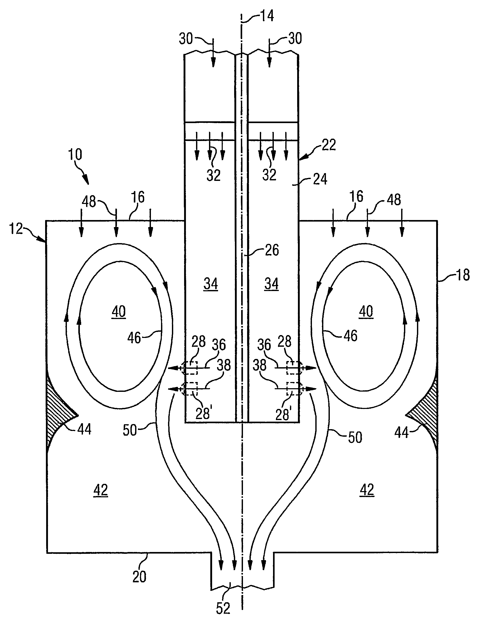
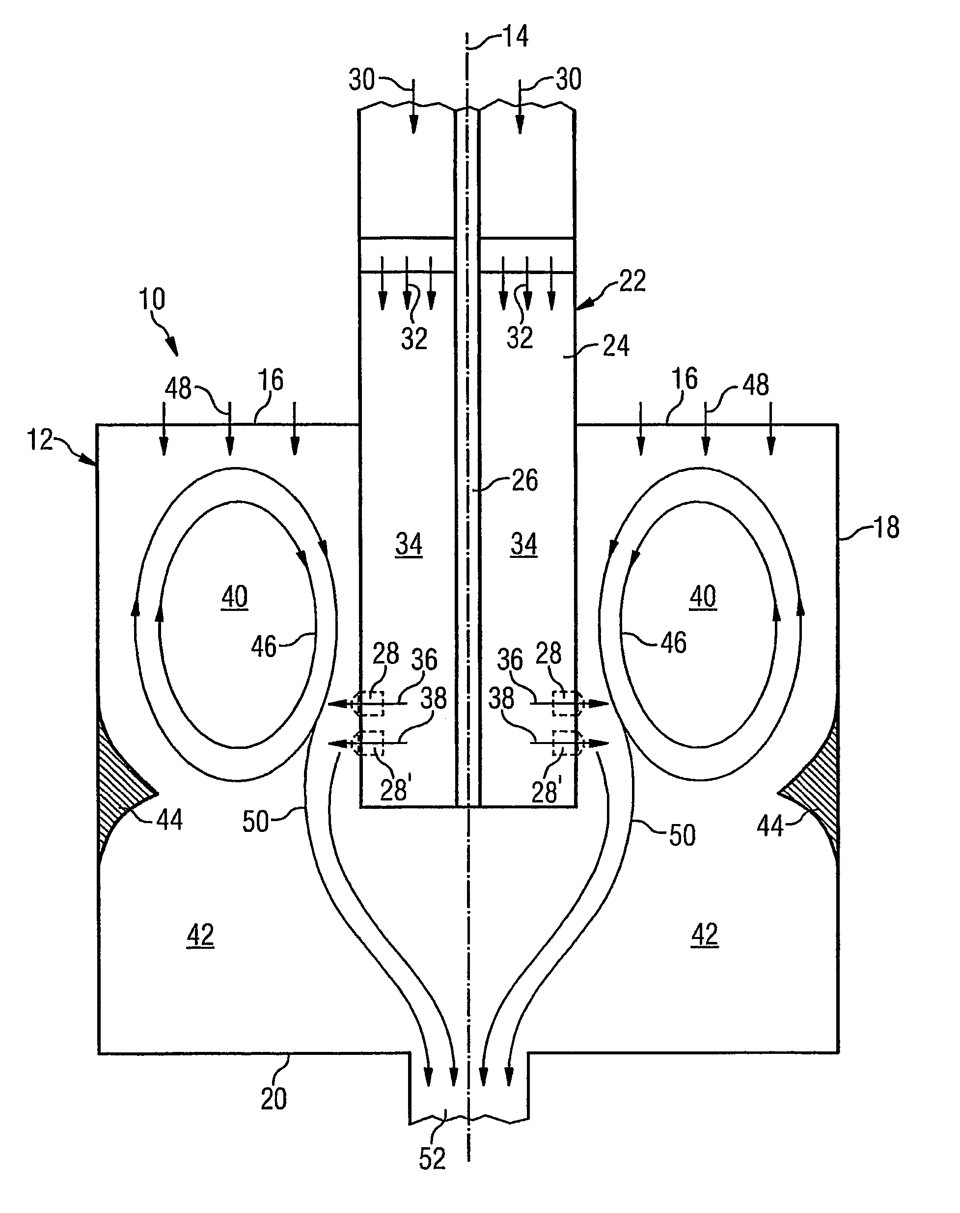
[0021] A device 10 for the combustion of fuel in a combustion chamber is illustrated in FIG. 1 in the form of a burner for a stationary gas turbine. An essential component of the device 10 is a combustion chamber 12 which is essentially designed in the form of a circular cylinder along an axis 14. The combustion chamber 12 is formed to include a first end wall 16 which is shown at the top in FIG. 1, an outer wall 18 which extends downwards from said face wall, and a second face wall 20 which is shown at the bottom in FIG. 1.

[0022] A centrally arranged body 22, which essentially has the form of a circular cylinder and likewise extends along the axis 14, passes through the first face wall 16. The body 22 is configured to include an outer tube 24 and an inner tube 26 which is arranged concentrically therein. Nozzles 28 which are oriented radially outwards pass though the outer tube 24, and are located at the lower end region of the outer tube 24 with reference to FIG. 1. The outer tub...


PUM


Abstract

A method and device for the combustion of fuel in a fuel chamber resulting in combustion which is particularly low in nitrogen, wherein fuel and combustion air are mixed before entering the combustion chamber avoiding self-ignition; a first part of the mixture is introduced into the combustion chamber such that it circulates inside the combustion chamber; other fuel is added to the circulatory flow of the first part of the mixture until it is heated up to ignition conditions; and at least one second part of the mixture is introduced into the combustion chamber in such a way that is mixed with hot combustion gas from the circulatory flow, heated up and combusted until it leaves the combustion chamber.

Description

CROSS REFERENCE TO RELATED APPLICATIONS [0001] This application is the US National Stage of International Application No. PCT / EP2004 / 011490, filed Oct. 13, 2004 and claims the benefit thereof. The International Application claims the benefits of European application No. EP03023210.2 filed Oct. 13, 2003, both of the applications are incorporated by reference herein in their entirety.FIELD OF THE INVENTION [0002] The invention relates to a method and a device for the combustion of fuel in a combustion chamber. BACKGROUND OF THE INVENTION [0003] The conventional method for converting fuel energy into heat is the oxidation or combustion of liquid fuel or gaseous fuel using an oxidizing agent such as atmospheric oxygen, for example. In the heavily loaded combustion systems of today, the problem exists in general that these systems must be configured for very low emissions, in particular for low NOx emissions. The combustion systems are expected to allow stable and complete combustion acr...

Claims


Application Information

Patent Timeline
IPC IPC(8): F23D11/44F23R3/34F23R3/36
CPCF23R3/34F23R3/36
Inventor LAUER, GERALD
Owner SIEMENS AG
Why Eureka
Try Eureka