Shaped walls for enhancement of deflagration-to-detonation transition

Active Publication Date: 2007-06-28
GENERAL ELECTRIC CO
View PDF9 Cites 33 Cited by
  • Summary
  • Abstract
  • Description
  • Claims
  • Application Information

AI Technical Summary

Benefits of technology

[0006] Exemplary embodiments also include a pulse detonation engine including: a pulse detonation combustor; a gas supply section for feeding a gas into the detonation chamber; a fuel supply section for feeding a fuel into the detonation chamber; an igniter for igniting a mixture of the gas and the fuel in the detonation chamber, wherein the pulse detonation combustor comprises a plurality of dimples disposed on an inner surface of the detonation chamber and a protrusion which is integral to the inner surface of the detonation chamber, extending into the detonation chamber; and wherein the plurality of dimples enhance a turbulence of a fluid flow through the detonat

Problems solved by technology

The problem with obstacles for cyclic detonation devices is tha

Method used


Image

  • Shaped walls for enhancement of deflagration-to-detonation transition
  • Shaped walls for enhancement of deflagration-to-detonation transition
  • Shaped walls for enhancement of deflagration-to-detonation transition

Examples


Embodiment Construction

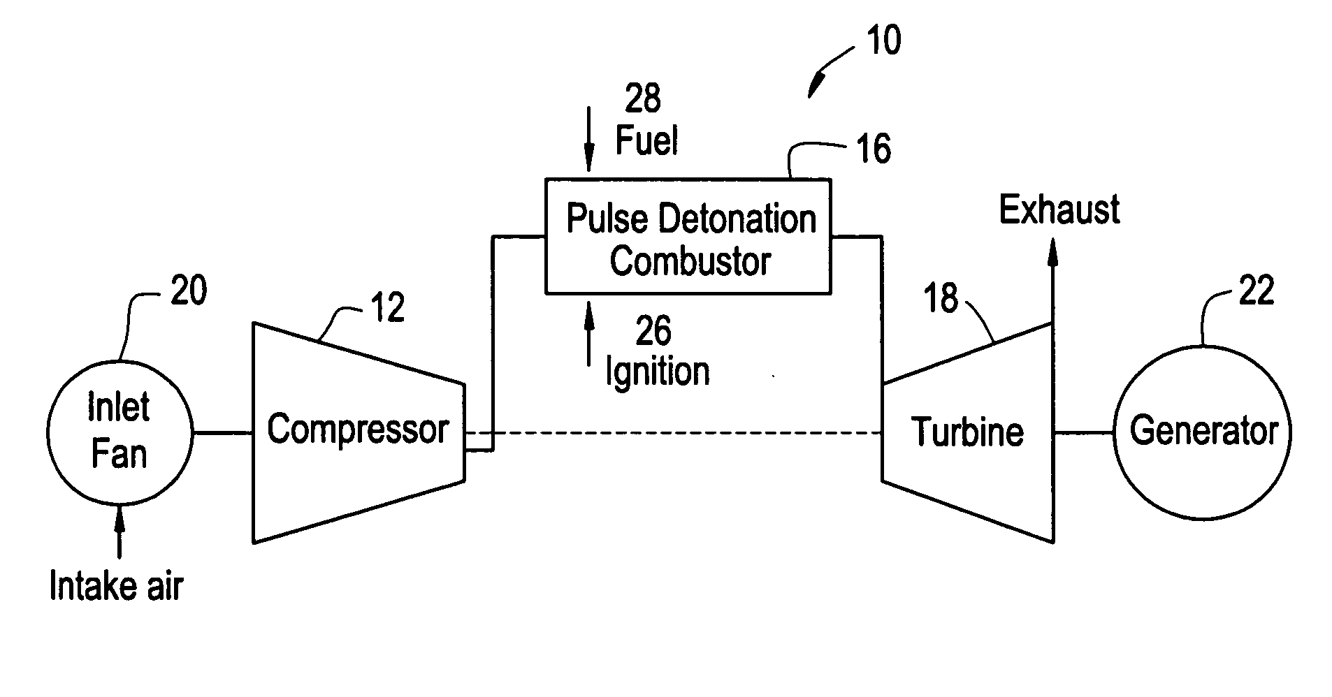
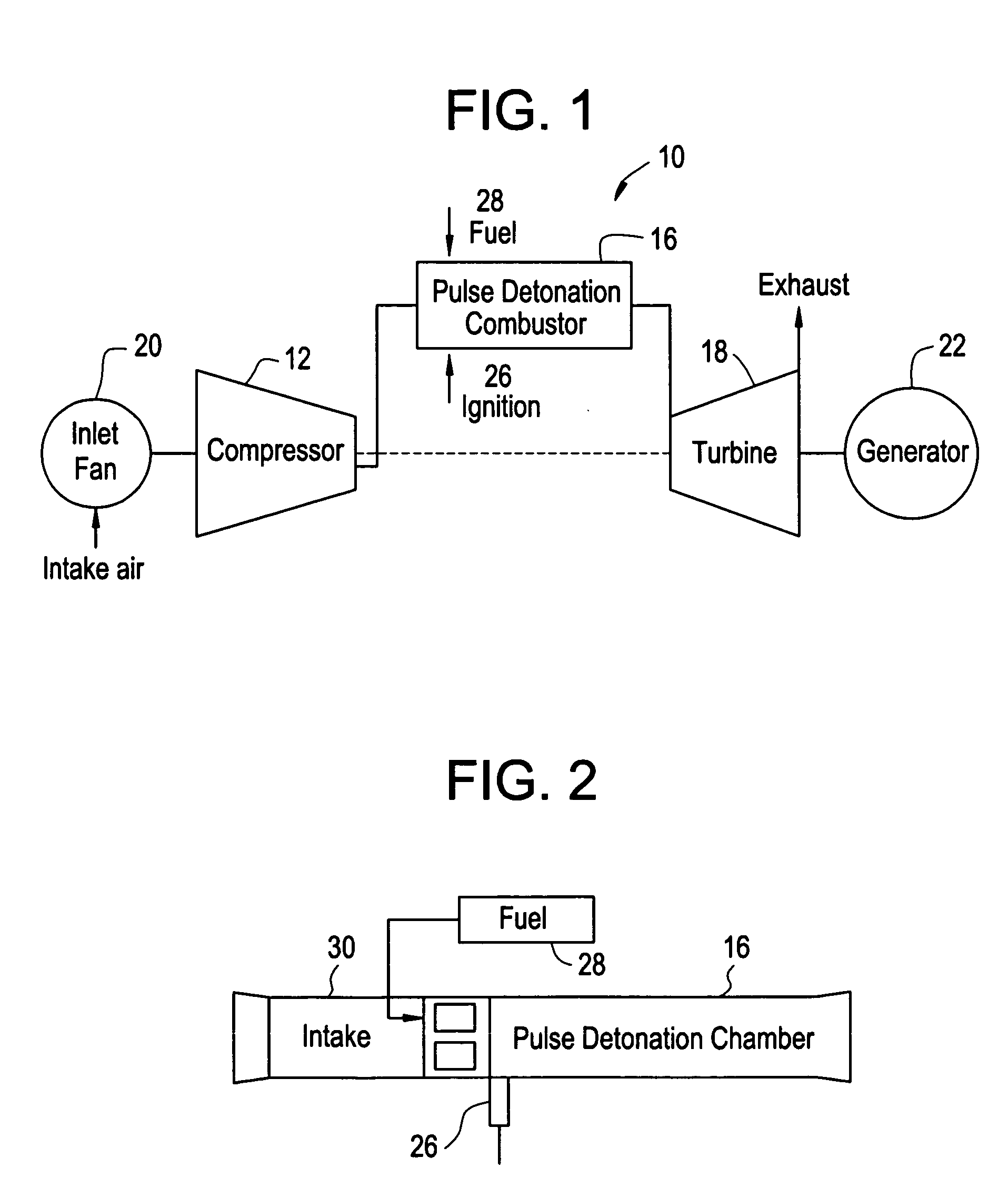
[0015] Referring now to FIGS. 1 and 2, various pulse detonation engine systems 10 convert kinetic and thermal energy of the exhausting combustion products into motive power necessary for propulsion and / or generating electric power. FIG. 2 shows a pulse detonation combustor in a pure supersonic propulsion vehicle. The pulse detonation combustor in a hybrid engine concept 10, shown in FIG. 1, or a pure pulse detonation engine shown in FIG. 2, includes a detonation chamber 16 having a gas supply section (e.g., an air valve) 26 for feeding a gas (e.g., oxidant such as air) into the detonation chamber 16, a fuel supply section (e.g., a fuel valve) 28 for feeding a fuel into the detonation chamber 16, and an igniter (for instance, a spark plug) 26 by which a mixture of gas combined with the fuel and air in the detonation chamber 16 is ignited.

[0016] In exemplary embodiments, air supplied from an inlet fan 20 and / or a compressor 12, which is driven by a turbine 18, is fed into the gas sup...


PUM


Abstract

A detonation chamber for a pulse detonation combustor including: a plurality of dimples disposed on at least a portion of an inner surface of the detonation chamber wherein the plurality of dimples enhance a turbulence of a fluid flow through the detonation chamber

Description

BACKGROUND [0001] The present disclosure generally relates to cyclic pulsed detonation combustors (PDCs) and more particularly, the enhanced mixing and turbulence levels of the fuel-air mixture and flame kernel in order to promote the deflagration-to-detonation transition process. [0002] In a generalized pulse detonation combustor, fuel and oxidizer (e.g., oxygen-containing gas such as air) are admitted to an elongated combustion chamber at an upstream inlet end. An igniter is used to initiate this combustion process. Following a successful transition to detonation, a detonation wave propagates toward the outlet at supersonic speed causing substantial combustion of the fuel / air mixture before the mixture can be substantially driven from the outlet. The result of the combustion is to rapidly elevate pressure within the combustor before substantial gas can escape through the combustor exit. The effect of this inertial confinement is to produce near constant volume combustion. Such dev...

Claims


Application Information

Patent Timeline
IPC IPC(8): F23R7/00
CPCF23R7/00
Inventor PINARD, PIERRE FRANCOISTANGIRALA, VENKAT ESWARLURASHEED, ADAMDEAN, ANTHONY JOHNBUNKER, RONALD SCOTTCHAPIN, DAVID MICHAEL
Owner GENERAL ELECTRIC CO
Why Eureka
Try Eureka