Methods and systems for debonding substrates

a technology of debonding substrates and methods, applied in the field of bonded substrate materials, can solve the problems of inaccessible effective removal tools, collateral damage to the surrounding structure of the aircraft, damage to the parent material of the substrate, etc., and achieve the effect of reducing or substantially eliminating temperature level errors and precise control of the temperature of the substra

Inactive Publication Date: 2007-06-28
L 3 INTEGRATED SYST +1
View PDF18 Cites 47 Cited by
  • Summary
  • Abstract
  • Description
  • Claims
  • Application Information

AI Technical Summary

Benefits of technology

[0012] Using the disclosed methods and systems, automated control of substrate temperature may be advantageously employed to reduce or substantially eliminate temperature level errors during heating that could lead to substrate damage, such as warping of the substrate or adverse heat treating effects to the substrate that may occur when excessive heat is applied. In this regard, automated control of substrate heating may be employed to achieve substantially precise control of substrate temperature and / or to ensure compliance with desired maximum temperatures or temperature ranges. Use of remote thermal sensors to monitor temperature during heating may be advantageously employed without requiring thermocouples to be placed in contact with the substrate to monitor the temperature of the substrate. Advantageously this allows heating of composite materials for composite repairs without the presence of thermocouples that may interfere with the composite repair material.

Problems solved by technology

Many times such sealant bonds are inaccessible to effective removal tools.
However, the use of a prying force to separate aircraft substrates often results in damage to parent material of the substrate and collateral damage to the surrounding structure of the aircraft, as well as damage to the tools employed.
However, phenolic scrapers have been found to be brittle.
However, placement and removal of heat blankets is a time consuming process and proper placement is limited by the size of the heat blanket relative to the size and accessibility of the bonded substrates.
In this regard, the location of the substrate parts being debonded directly impact heat blanket accessibility, and parts located within certain areas of an aircraft complicate the utilization of heat blankets for debonding.
Placement of the heat blankets in contact with substrates on the underside of horizontally oriented areas is an awkward process since the heat blankets are pulled away from these substrates by gravity.

Method used


Image

  • Methods and systems for debonding substrates
  • Methods and systems for debonding substrates
  • Methods and systems for debonding substrates

Examples


Embodiment Construction

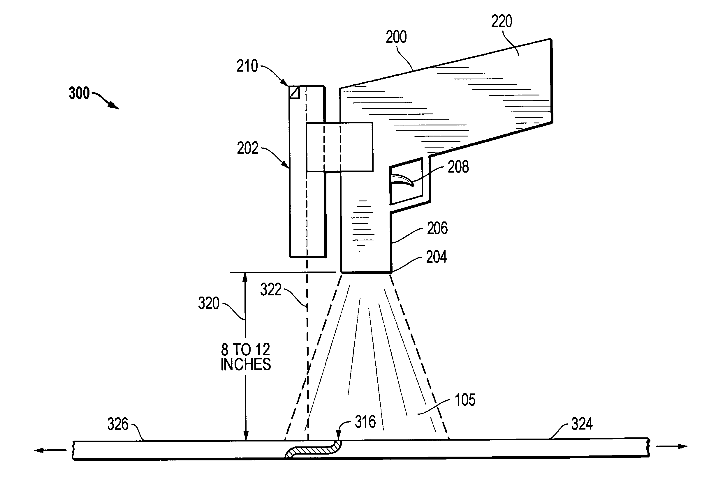
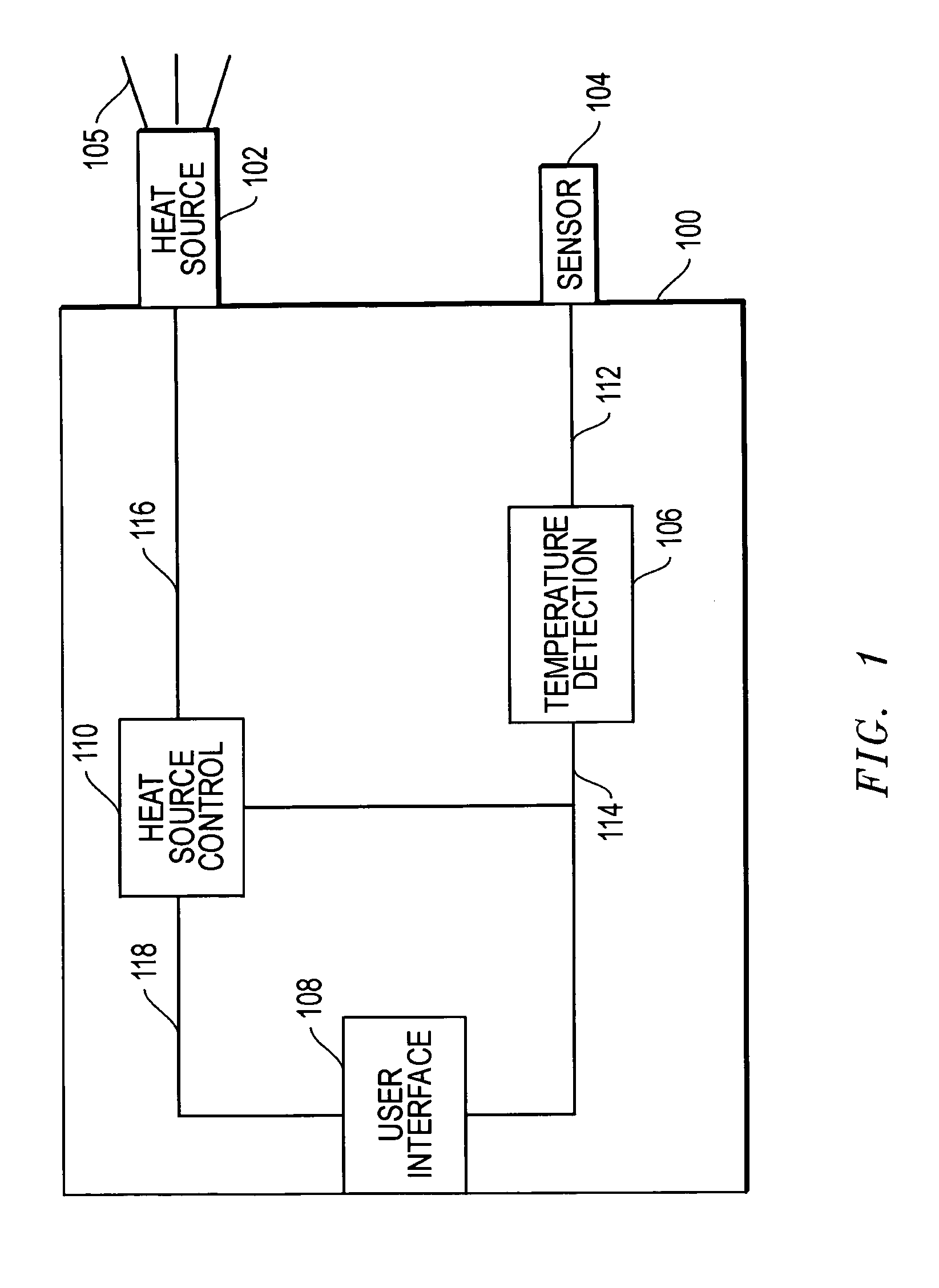
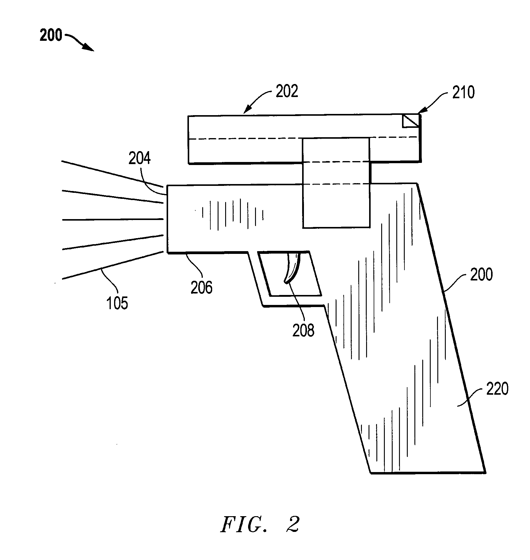
[0026]FIG. 1 shows a block diagram of a substrate heating system 100 according to one exemplary embodiment of the disclosed methods and systems that may be implemented, for example, to separate two or more substrates bonded by bonding material. As shown, system 100 includes a heat source 102 configured to emit heat 105 (e.g., radiant or convective heat), that is controlled by a heat source control 110 based at least partially on temperature information provided by temperature detector 106 and thermal sensor 104. System 100 also includes a user interface 108 that may be present, for example, to allow a user to input control information to a heat source control 110 and / or for display of heating system operation information to a user.

[0027] Still referring to FIG. 1, heat source 102 may be any one or more components suitable for remotely applying heat (e.g., radiant or convective heat) to a substrate, i.e., without making physical contact with the substrate. Examples of suitable remot...


PUM

PropertyMeasurementUnit
temperaturesaaaaaaaaaa
distanceaaaaaaaaaa
temperatureaaaaaaaaaa

Abstract

Methods and systems for applying heat to substrates that are in contact with an uncured bonding material or that are bonded with one or more sealants or other bonding material/s. Substrates may be heated, for example, so that the substrates may be debonded by degrading one or more mechanical properties of the bonding material/s so that the substrates may be separated. The application of heat to a substrate may be controlled based on the temperature of the substrate during the heating process. Damage-sensitive substrates, such as aircraft substrates, may be heated in a manner that controls surface temperature of the substrates to meet heat treating requirements and/or to limit heating to maximum temperatures for the substrates in a manner that substantially eliminates damage to the substrates during the heating operation while at the same time at least partially curing uncured bonding material, or degrading one or more mechanical properties of cured bonding material/s.

Description

FIELD OF THE INVENTION [0001] This invention relates generally to bonded substrate materials, and more particularly to methods and systems for debonding or separating bonded substrates, or for at least partially curing uncured bonding material in contact with a substrate. BACKGROUND OF THE INVENTION [0002] Damage-sensitive substrates, such as aircraft substrates, are often bonded together by sealant. One example of such sealants is polysulfide sealant that is employed to control corrosion and eliminate leaks. Such sealants may be applied to bond and seal fay surfaces of an aircraft aluminum structure in areas such as skin laps, wing skin to structure, circumferential and longitudinal skin splices, skin-to-stringer and skin-to-shear tie joints in the lower lobe of a fuselage, skin doublers, wheel well structure, spar web-to-chord and chord-to-skin joints of wing and empennage, and pressure bulkheads. Many times such sealant bonds are inaccessible to effective removal tools. [0003] Ce...

Claims


Application Information

Patent Timeline
Patent Type & Authority Applications(United States)
IPC IPC(8): B29C63/00H05B1/02
CPCB29C65/14Y10T156/19B29C66/003B29C66/861B29C66/90B29C66/91216B29C66/91221B29L2031/3076B29C65/10B29C66/1282B29C66/12881B29C65/103B29C66/91411B29C66/91431B29C66/91443B29C66/91641B29C66/91212B29C66/836B29C66/961B29C65/76B29C66/43
Inventor PADILLA, KENNETHGRANT, CHADTHRELFALL, JAMES
Owner L 3 INTEGRATED SYST
Why Eureka
Try Eureka