Rotor for generating vortex water flow, and filtering apparatus employing the same

a technology of vortex water and rotor, which is applied in the direction of wind motor with parallel air flow, water/sewage treatment bu osmosis/dialysis, wind motor with perpendicular air flow, etc. it can solve the problems of increasing manufacturing costs, affecting the efficiency of filtering apparatus in precessing polluted water, and affecting the separation of liquid(or gas) solids. the effect of the separation membran

Active Publication Date: 2007-06-28
BKT
View PDF15 Cites 40 Cited by
  • Summary
  • Abstract
  • Description
  • Claims
  • Application Information

AI Technical Summary

Benefits of technology

[0028] The filter tray is fixed in the barrel, and has at least one of water passage port so formed as to penetrate a plane thereof. The water in the barrel can flow smoothly in the barrel through the water passage port.
[0029] The filter tray includes a supporting plate having a disk shape, a drain cloth attached on both surface of the supporting plate, and a separation membrane attached to an outer surface of the drain cloth, and the drain cloth and the separation membrane are adhered onto the supporting plate with thermosetting adhesive. T...

Problems solved by technology

The problem hardest to overcome in such a liquid-solid separation technique using the porous membrane is the abrupt declination of the liquid(or gas)-solid separation capacity of the separation membrane as the size of the pores that are the passages of the filtered liquid is reduced or the pores are blocked by the solid material adhered to the surface of the separation membrane or to the inner surface of the pores during the separation process.
However, the shear rate on the surface of the membrane by the relative movement decreases seriously as the distance between the separation membrane and the disk becomes great.
If the distance between the separation membrane and the disk becomes small in order to increase the shear rate, the separation membrane and the disk may contact with each other by the pressure difference between both sides of the disk to cause the damage on the membrane, so the precise treatment and accurate assembly are required to prevent such a problem, which may cause the increase of the manufacturing costs.
However, that causes the increase of the driving costs and management costs, which deteriorates the economical performance of the system.
However, the increase of the shear rate of the fluid at the surface of the membranes merely with the change of the speed of fluid by the relative movement of separation membran...

Method used


Image

  • Rotor for generating vortex water flow, and filtering apparatus employing the same
  • Rotor for generating vortex water flow, and filtering apparatus employing the same
  • Rotor for generating vortex water flow, and filtering apparatus employing the same

Examples


first embodiment

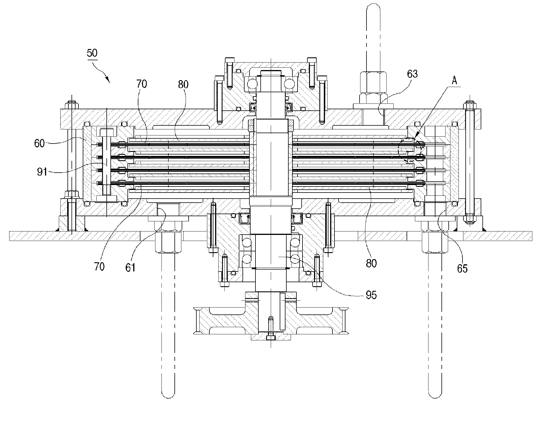
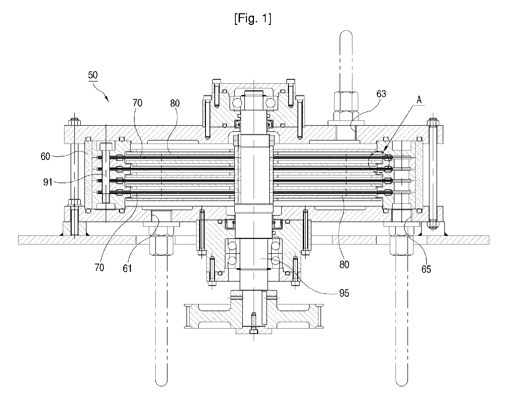
[0060]FIG. 4 is a view showing the rotor for generating vortex water flow according to the present invention, and FIG. 5 is an enlarged view of part A in FIG. 1 including the cross section along the line I-I of FIG. 18.

[0061] The rotor 100 for generating vortex water flow according to the first embodiment of the present invention is comprised of a first rotor 110 and a second rotor 120. An assembly ring 150 assembled with the rotational shaft 95 of the filtering apparatus 50 is prepared at the central area of the rotor 100, and the assembly ring 150 is assembled with the first rotor 110 and the second rotor 120. Accordingly, the rotor 100 assembled with the rotational shaft 95 through the assembly ring 150 is rotated by the rotational shaft 95 when the rotational shaft 95 is rotated.

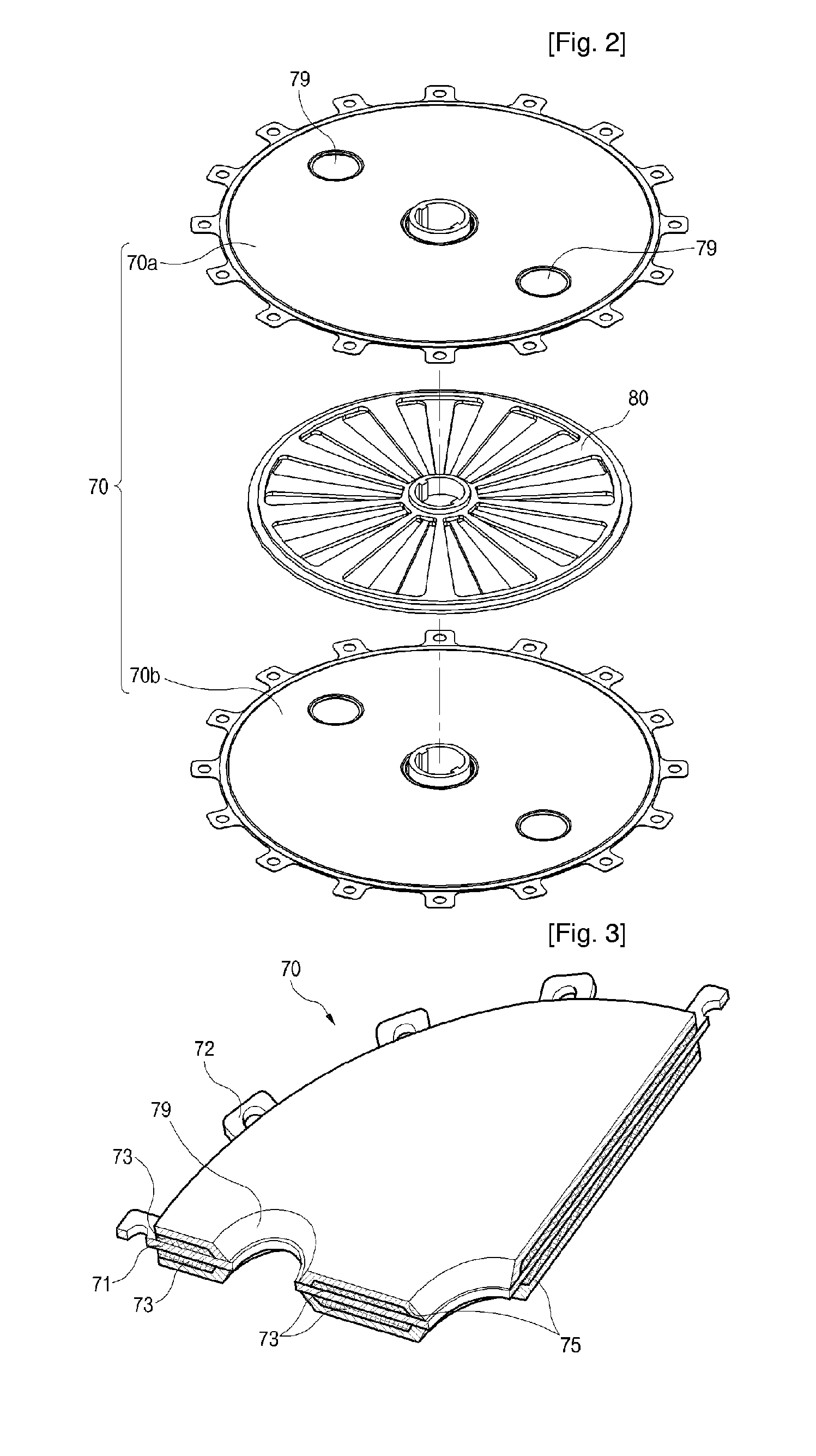
[0062] The first rotor 110 has a plurality of first blades 111 extended from the rotational axis in the radial direction thereof. A first assembly portion 115 having a shape of a ring assembled with the...

second embodiment

[0068] In the second embodiment, the first blades 211 and the second blades 221 are disposed at positions different from each other in the circumferential direction around the rotational axis of the rotor 200. More particularly, the first blades 211 and the second blades 221 have the same shape and width with each other, and only the arranged positions thereof are different.

[0069] As shown in FIGS. 8 and 9, the first blades 211 and the second blades 222 are partially overlapped with each other, in other words, about half of the width thereof is overlapped. According to such a construction, as shown in FIG. 10, the position that the vortex water is generated by the upper blades 211 at the front area and the rear area in the rotational direction is different from the position that the vortex water is generated by the lower blades 221 at the front and the rear area in the rotational direction. Thus, more complex vortex water flow can be generated effectively in comparison with the case...

third embodiment

[0070]FIG. 11 is a view showing the rotor for generating vortex water flow according to the present invention, and FIG. 23 is a cross sectional view of FIG. 11 along the line II-II.

[0071] In the third embodiment, the first blades 311 and the second blades 321 are disposed at positions different from each other in the circumferential direction around the rotational axis of the rotor 300, and simultaneously, are distanced from each other in the circumferential direction. Furthermore, the first blades 311 and the second blades 321 are so disposed as to be distanced equally from each other in the circumferential direction. The width and the shape of the first blades 311 and the second blades 321 are same with each other. Therefore, as shown in FIG. 12, the first blades 311 and the second blades 321 are arranged in a zigzag manner.

[0072] According to such a construction, the vortex water flow as shown in FIG. 13 is formed. As shown in FIG. 13, the respective blades 311 and 321 generate ...


PUM

PropertyMeasurementUnit
Sizeaaaaaaaaaa
Shapeaaaaaaaaaa
Widthaaaaaaaaaa

Abstract

Disclosed are a rotor for generating vortex water flow that creates shear intensity for removing solid material adhered to the separation membranes during the processing of water containing pollutant material, and a filtering apparatus employing the same. The rotor consists of a first rotor having first blades and a second rotor having second blades. The first and the second blades are extended in a radial direction from a rotational axis thereof, and are disposed at positions different from each other in the rotational axis direction. The first blades and the second blades have widths different from each other in a circumferential direction around the rotational axis, or disposed at positions different from each other in a circumferential direction. Protrusions can be attached on outer surfaces of the first blades and/or second blades. The pollutant material adhered to the separation membrane can be removed effectively since various types of vortex water flow are generated over wide range, and the energy loss of the filtering apparatus is reduced.

Description

TECHNICAL FIELD [0001] The present invention relates to a rotor for generating vortex water flow and a filtering apparatus employing the same, and more particularly, to a separation membrane filtering apparatus for filtering pollutant in water containing the pollutant material to a clean purified water, and a rotor for generating vortex water flow employed in the same. BACKGROUND ART [0002] The filtering apparatus for purifying water by filtering the pollutant in the polluted water is generally equipped with a porous membrane through which the polluted water passes. The pollutant in the polluted water is filtered by the porous membrane, by which the water passing through the porous membrane is discharged as a clean water. [0003] The problem hardest to overcome in such a liquid-solid separation technique using the porous membrane is the abrupt declination of the liquid(or gas)-solid separation capacity of the separation membrane as the size of the pores that are the passages of the f...

Claims


Application Information

Patent Timeline
IPC IPC(8): B01D33/00B01D25/26B01D63/08B01D65/08B01F7/00
CPCB01D25/26B01D63/084B01D65/08B01D2321/30B01F7/00758B01D25/288B01F27/271G07D11/0087G07D1/04G07F7/04G07D2211/00
Inventor PARK, GI-TEAKKIM, SANG-WOOK
Owner BKT
Why Eureka
Try Eureka