Optical prism and optical transceiver module for optical communications

Inactive Publication Date: 2007-06-28
HITACHI LTD
View PDF4 Cites 28 Cited by
  • Summary
  • Abstract
  • Description
  • Claims
  • Application Information

AI Technical Summary

Benefits of technology

[0009]Each of these Patent Documents shows an optical transceiver module designed to reduce the number of components for downsizing. In assembling the module, however, it may be difficult to accurately position each component for assembling the module while securing a specified optical coupling efficiency.
[0010]The present invention was made in view of the above-mentioned problems. It is a first object of the present invention to provide an optical prism for optical communications

Problems solved by technology

In assembling the module, however, it may be difficult to accurately position each comp

Method used


Image

  • Optical prism and optical transceiver module for optical communications
  • Optical prism and optical transceiver module for optical communications
  • Optical prism and optical transceiver module for optical communications

Examples


Example

Embodiment 1

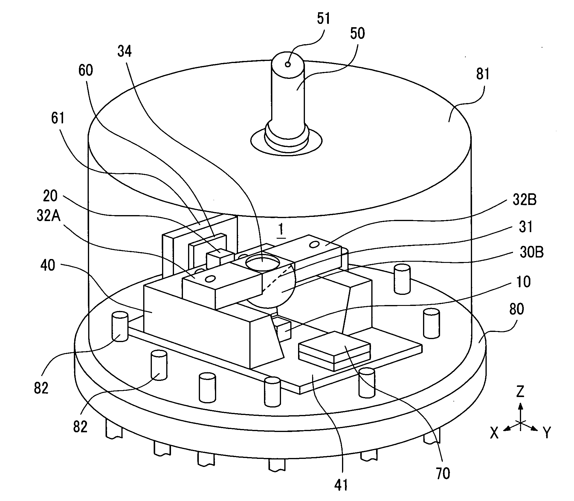
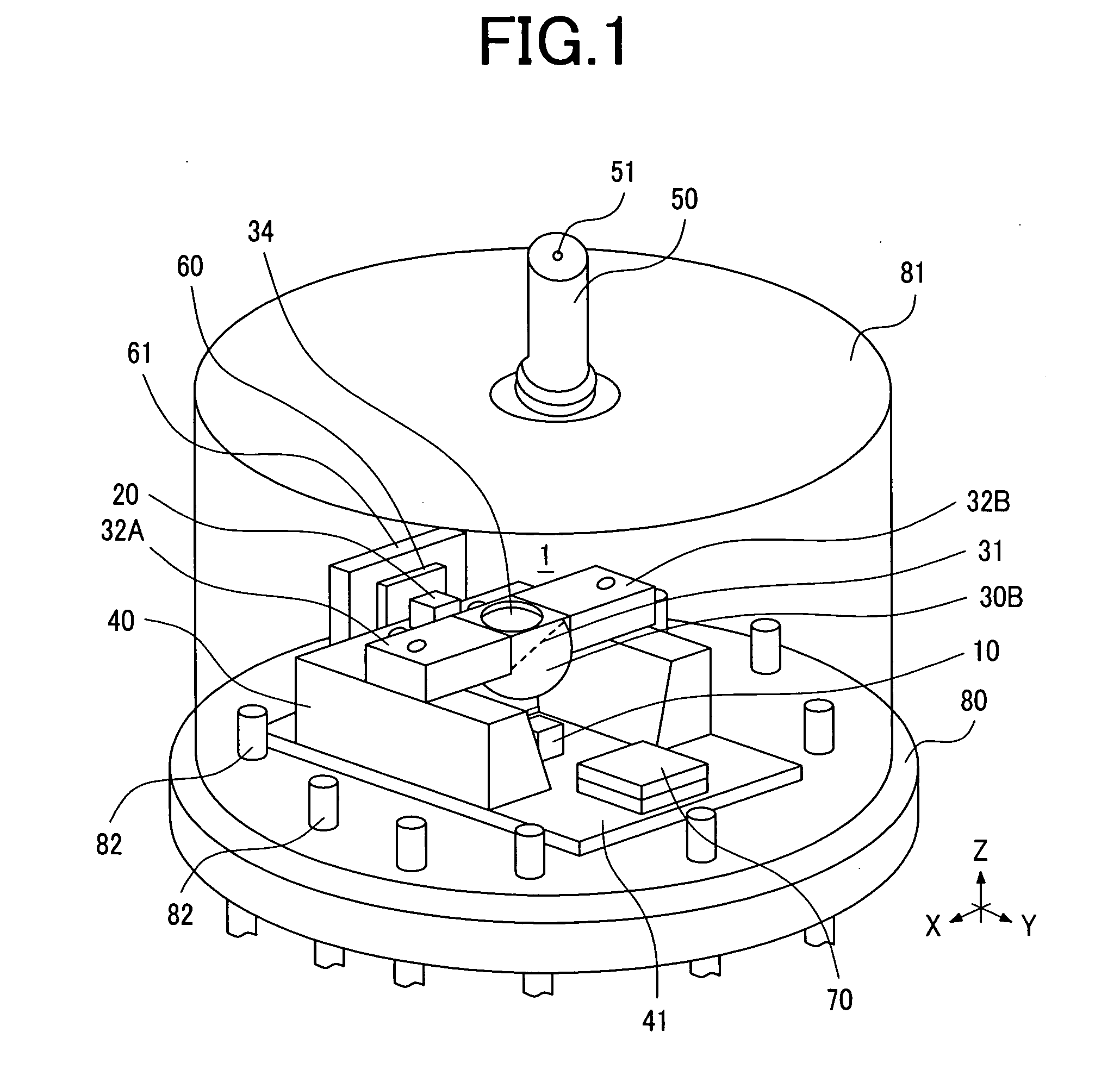
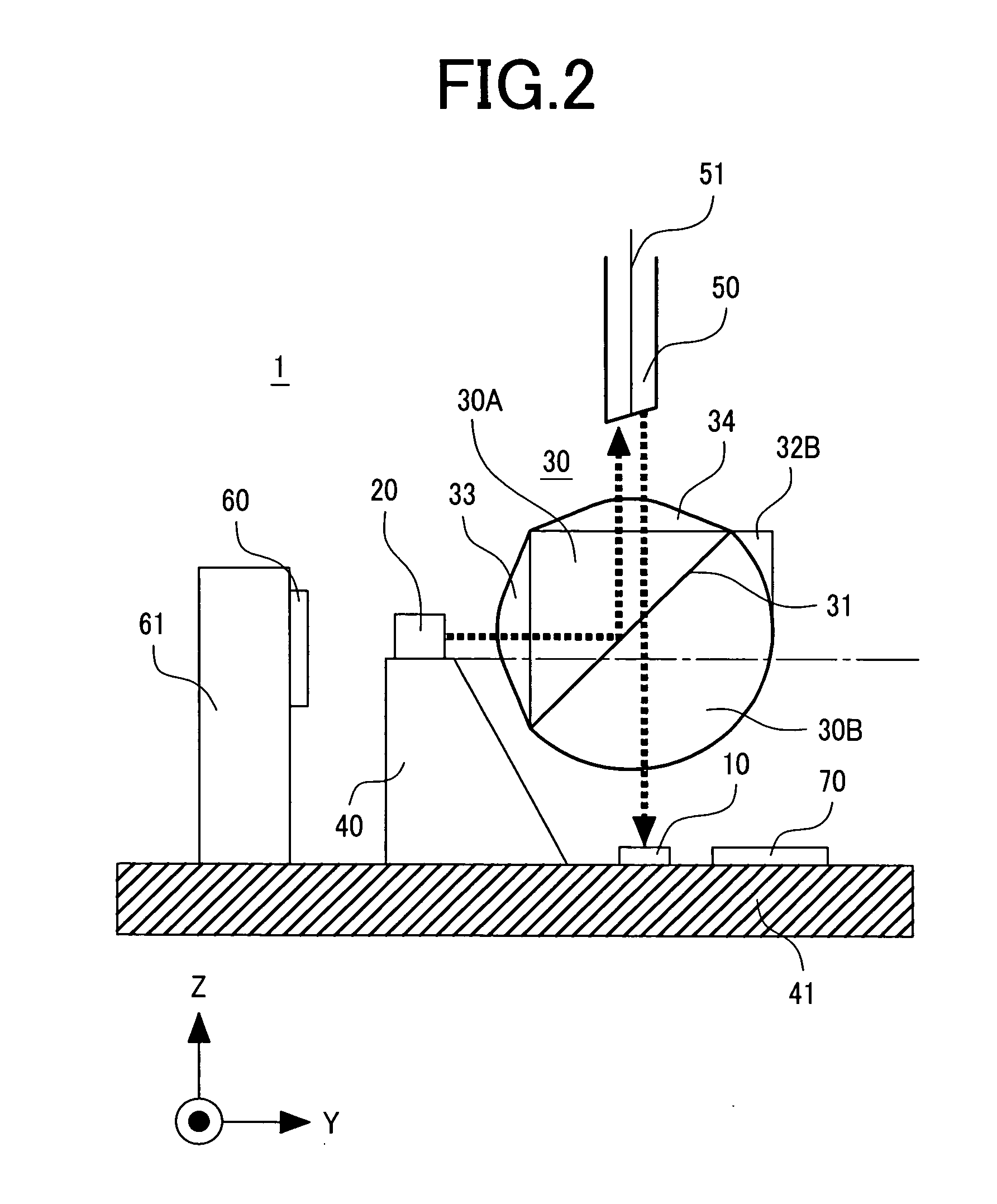
[0022]With reference to FIGS. 1 and 2, the following describes the configuration of an optical transceiver module having an optical prism for optical communications according to a first embodiment of the present invention. FIG. 1 schematically illustrates the configuration of the optical transceiver module according to the first embodiment of the present invention. FIG. 2 is an enlarged cross section view of the optical transceiver module shown in FIG. 1. FIG. 2 shows the individual configurations and mutual relationships of a substrate, a sub-mount structure, and main components (laser diode, photo diode and optical fiber) of the optical transceiver module.

[0023]The optical transceiver module (hereinafter referred to as an “optical module”) 1 shown in FIG. 1 may be provided as part of an optical network unit (ONU) to perform bidirectional communications using wavelength division multiplexing (WDM) transmission. The optical module 1 is mounted on a can package base 80 an...

Example

[0032]FIGS. 3B(A) to 3B(D) show a variation of the first embodiment shown in FIGS. 3A(A) to 3A(D). While the optical communication prism 30 of the first embodiment is configured by combining the right-angled prism 30A with the hemisphere prism 30B, the optical prism 30 of this variation is configured by combining the right-angled prism 30A with another right-angled prism 30A′. The right-angled prism 30A′ and right-angled prism 30A in plane symmetry with respect to the slant surfaces.

[0033]FIGS. 3B(A) to 3B(D) correspond with FIGS. 3A(A) to 3A(D), respectively. Comparing the two types, only the the hemisphere lens 30B (hemisphere prism) is replaced with the right-angled prism 30A′. Thus, there is little difference between the two types. One of the changes is that an optical element, namely a convex lens 34′ is formed on one of the two surfaces forming a right angle of the right-angled prism 30A′ since the right-angled prism 30A′ does not have a convex lens function, not like the hemi...

Example

Embodiment 2

[0040]In the optical prism 30 of the first embodiment mentioned above, the wavelength division multiplexing filter 31 is directly stuck to the slant surface (joint surface) of the right-angled prism 30A and that of the hemisphere lens 30B. Therefore, these joint surfaces are coated with an adhesive such as a ultra-violet cured resin. In a second embodiment, a concave portion, thicker than the wavelength division multiplexing filter 31, is formed in the slant surface of the hemisphere lens 30B. The wavelength division multiplexing filter 31 is set in this convex portion.

[0041]FIG. 5(A) shows a cross section of the components constituting the optical prism 30 of the second embodiment. Concaves 35 are formed at both ends of the slant surface 30C of the right-angled prism 30A. As mentioned above in the description of the first embodiment, the slant surface 30D (indicated by a broken line) of the hemisphere lens 30B has convexes 39 formed at both ends for engagement with the ...


PUM


Abstract

To provide an optical transceiver module comprising an optical prism for optical communications which has mounting portions, a light emitting portion, light receiving portions, a substrate and a sub-mount that are used as the basis of the optical transceiver module, whose configuration is compact with reduced components which are accurately mounted.
A sub-mount is provided on the substrate. The composite optical prism is formed with an optical lens provided with mounting supports and a wavelength division film in an integrated fashion. By using marks on the sub-mount for alignment, the composite optical prism can be mounted accurately on the sub-mount. In addition, the light receiving portions and the light emitting portion can be mounted accurately by using marks for alignment provided on the substrate and the sub-mount.

Description

CLAIM OF PRIORITY[0001]The present application claims priority from Japanese application JP 2005-357689 filed on Dec. 12, 2005, the content of which is hereby incorporated by reference into this application.FIELD OF THE INVENTION[0002]The present invention relates to an optical system which comprises an optical prism for optical communications having a wavelength division multiplexing filter, a right-angled prism and a hemisphere lens, and mounting supports integrated with the optical prism for optical communications, and to an optical transceiver module in which a sub-mount is used to mount the optical system mounted on a substrate on which laser diodes for optical transmission and photo detectors for optical reception are formed.BACKGROUND OF THE INVENTION[0003]Since 2000, high-speed communications have rapidly proliferated due to ADSL (Asynchronous Digital Subscriber Line) services for which metal cables are used, changing the broadband services to high-speed Internet access. Fur...

Claims


Application Information

Patent Timeline
IPC IPC(8): G02B27/28G02B5/04G02B6/42
CPCG02B6/4246G02B7/1805H04B10/40
Inventor TANAKA, KEN'ICHISHISHIKURA, MASATOSEKINE, KENROSUGAWARA, TOSHIKIMATSUOKA, YASUNOBU
Owner HITACHI LTD
Why Eureka
Try Eureka