Battery electrode design and a flat stack battery cell design and methods of making same

a battery cell and flat-stack technology, applied in the direction of cell components, final product manufacturing, sustainable manufacturing/processing, etc., can solve the problems of limiting the shape and size of the grid used in the lead-acid battery, limiting the usefulness of additional active materials, and difficult to use active materials, so as to increase the effectiveness and utilization of active materials, reduce resistance, and facilitate manufacturing

Inactive Publication Date: 2007-06-28
EXIDE TECHNOLOGIES LLC
View PDF13 Cites 32 Cited by
  • Summary
  • Abstract
  • Description
  • Claims
  • Application Information

AI Technical Summary

Benefits of technology

[0010] It is an advantage of the present invention to overcome the problems of the related art and to provide a battery electrode plate design that locates the current collection point at a location that is more central to the plate, and a lead-acid battery design that utilizes this unique construction. This will, in turn, reduce the resistance between the current collection point and any other point on the grid structure; and thus increase the effectiveness and utilization of the active material applied to the grid in these areas. The resulting battery will be easier to manufacture, require fewer individual components, allow easy expansion of the product line (by the use of standardized grids, jars, and covers), and provide improved battery performance resulting from a lower internal resistance.
[0011] According to a first aspect of the present invention, a novel combination of structure and / or steps is provided for a lead-acid battery having a first electrode plate comprising (i) a frame, (ii) a plurality of intersecting conducting members forming a grid disposed in the interior of said frame, (iii) first and second collector pole access channels disposed in the interior of said frame, (iv) a coating of a lead-acid battery active material paste. A second electrode plate comprises (i) a frame, (ii) a plurality of intersecting conducting members forming a grid disposed in the interior of said frame, (iii) first and second collector pole access channels disposed in the interior of said frame, (iv) a coating of a lead-acid battery active material paste. A first current collector pole is configured to be installed in the first collector pole access channel of the first electrode plate and the first collector pole access channel of the second electrode plate. A second current collector pole is configured to be installed in the second collector pole access channel of the first electrode plate and the second collector pole access channel of the second electrode plate.
[0012] According to a second aspect of the present invention, a novel combination of structure and / or steps is provided for a lead-acid storage battery electrode grid having a frame, and a plurality of intersecting members forming a grid disposed interiorly of the frame. At least two disc slugs are disposed in the interior of the frame, the slugs being configured to be hole-punched to accommodate current collector poles through the punched holes.
[0013] According to a third aspect of the present invention, a novel combination of structure and / or steps are provided for a storage battery electrode plate having a frame, and a grid of elements disposed interiorly of the frame. A first collector pole access channel is disposed interiorly of the frame and orthogonal with respect to the grid of elements, and a second collector pole access channel is also disposed interiorly of the frame and orthogonal with respect to the grid of elements.
[0014] According to a fourth aspect of the present invention, a novel combination of steps is provided for a method of constructing a lead-acid battery, comprising the steps of: (i) providing first and second current collector poles; (ii) providing first and second electrode plates, each electrode plates comprising (a) a frame, (b) a plurality of intersecting conducting members forming a grid disposed interiorly of the frame, (c) first and second disc slugs disposed interiorly of the frame, and (d) a coating of a lead-acid battery active material paste; (iii) hole-punching the first slug of the first electrode plate forming a collector pole access channel configured to interference-fit with said first current collector pole; (iv) hole-punching the second slug of the first electrode to form a collector pole access channel configured to be larger than the outside diameter of said second current collector pole; (v) installing the first electrode onto the current collector poles and welding the first electrode to the first current collector pole at the interference-fit with the first collector pole access channel; (vi) covering the second electrode plate with a mat separator; (vii) hole-punching the first slug of the second electrode plate and separator to form a collector pole access channel configured to be larger than the outside diameter of the first current collector pole; (viii) hole-punching the second slug of the second electrode plate and separator to form a collector pole access channel configured to interference-fit with the second current collector pole; and (ix) installing the second electrode onto the current collector poles and welding the second electrode to the second current collector pole at the interference-fit with the second collector pole access channel.

Problems solved by technology

This means that the distance varies significantly from the plate lug to the various current-generation positions in the plate; thus the resistance from the lug to the various points on the plate varies, making utilization of the active material more difficult the further it is away from the plate lug.
The resistance effects related to the location of the lug on the grid can limit the usefulness of additional active material and can limit the shape and size of the grid used in a lead-acid battery.
However, none of these documents provides a solution to the problems noted above.

Method used


Image

  • Battery electrode design and a flat stack battery cell design and methods of making same
  • Battery electrode design and a flat stack battery cell design and methods of making same
  • Battery electrode design and a flat stack battery cell design and methods of making same

Examples


Embodiment Construction

1. Introduction

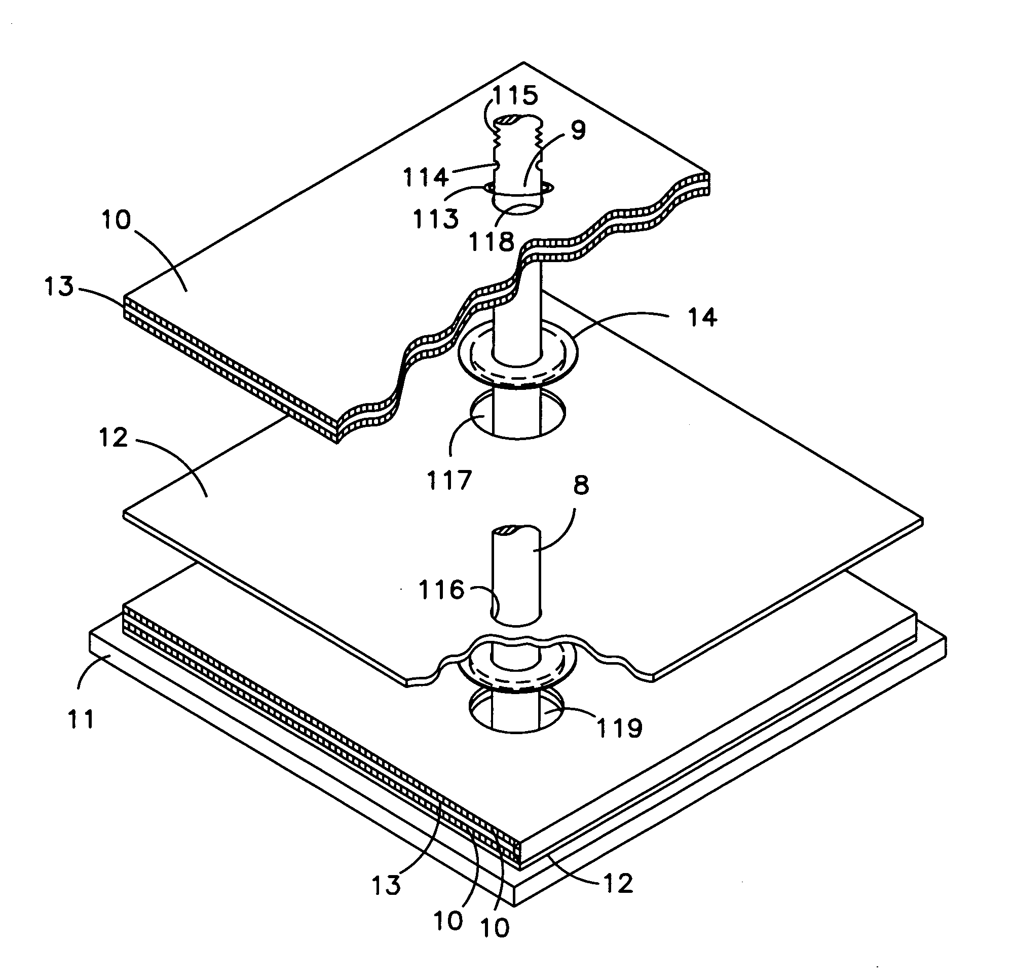
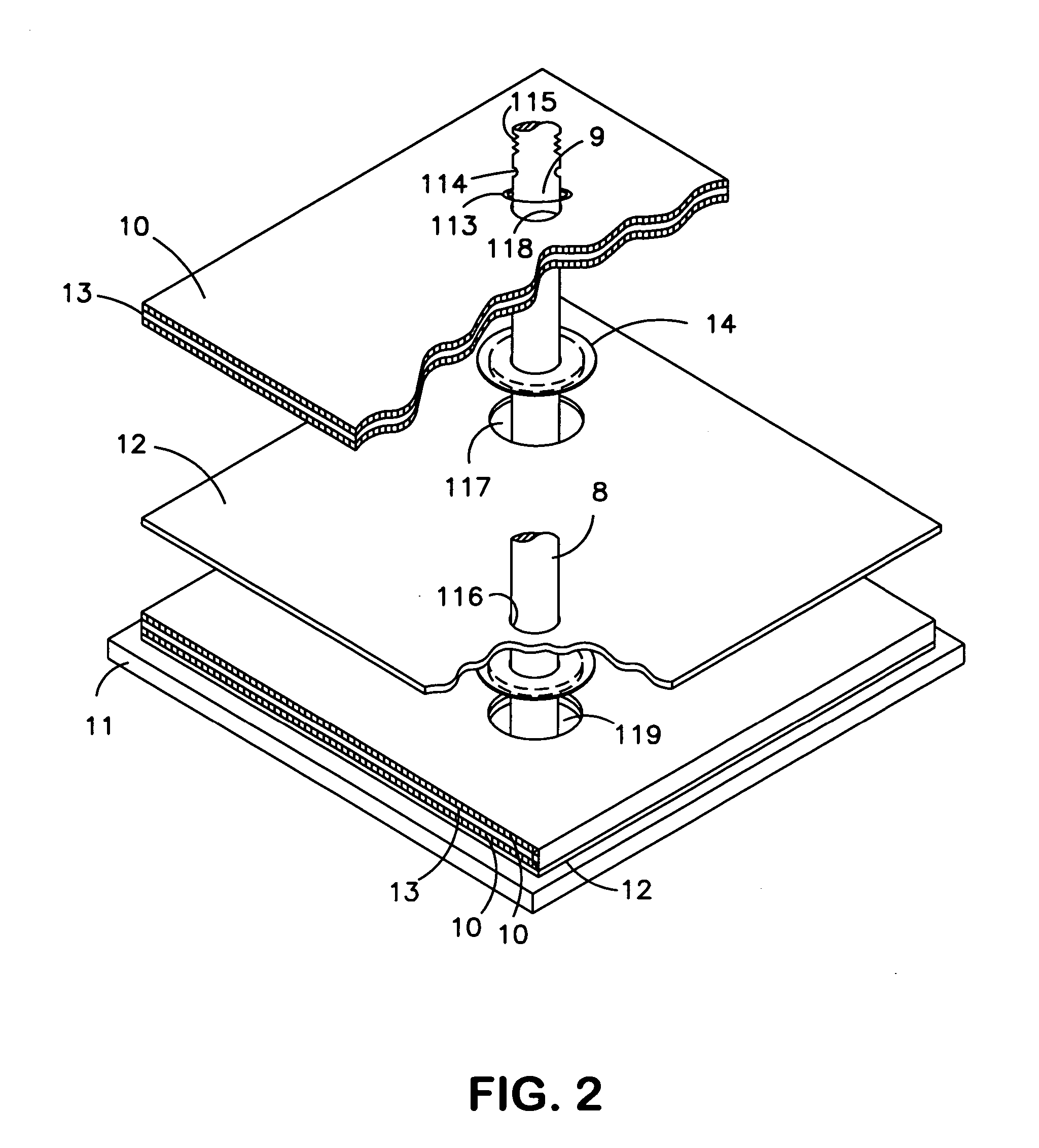
[0022] The present invention will now be described with respect to a Valve Regulated Lead-Acid (VRLA) battery having positive and negative plates, each comprising a rectangular matrix array of wire grids with an overlying active material paste. However, the present invention is applicable to any electrical storage battery cell having any type of positive and negative plates.

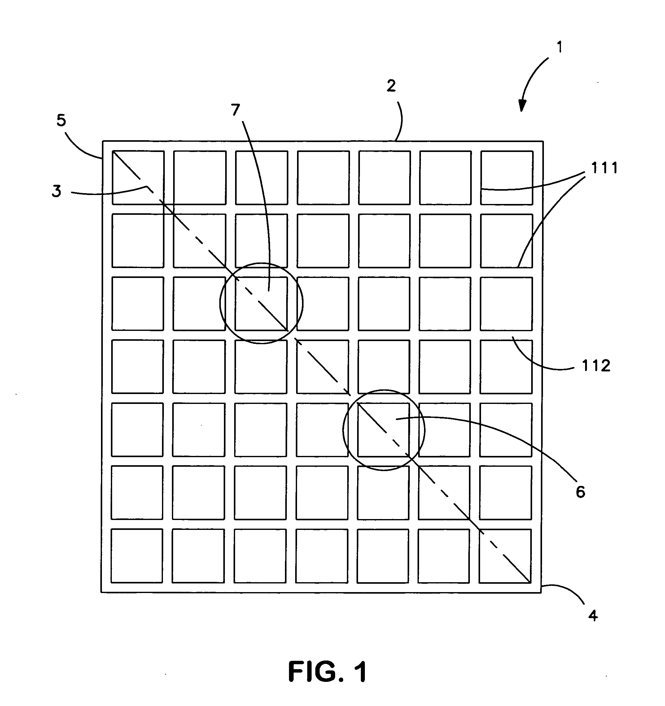
[0023] Briefly, the present invention proposes a battery electrode plate structure and method whereby each battery electrode grid includes two internally disposed collector pole access channels. Preferably, two lead slugs are formed interiorly of the electrode outer frame, preferably along a diagonal line, each slug being about ⅓ of the distance from opposite frame corners. During manufacturing, the slugs are punched out and collector poles are inserted into the holes of the stacked electrode plates (or the plates are stacked onto the poles). The negative collector pole, installed through one se...


PUM

PropertyMeasurementUnit
thicknessaaaaaaaaaa
thicknessaaaaaaaaaa
sizeaaaaaaaaaa

Abstract

A battery electrode design and a flat stack battery cell design preferably include structure and / or manufacturing steps whereby a battery electrode plate has a frame, and a grid-array of elements disposed interiorly of the frame. A first collector pole access channel is disposed interiorly of the frame and orthogonal with respect to the grid-array of elements, and a second collector pole access channel is also disposed interiorly of the frame and orthogonal with respect to the grid-array of elements. Preferably, the collector pole access channels are made by hole-punching lead slugs integrally disposed in the grid-array. Preferably, the electrode plates are a standard size, and may be disposed in a common jar; thus, the battery capacity is determined by the number of electrode plates in the jar, the jar being trimmed per the number of electrode plates.

Description

BACKGROUND OF THE INVENTION [0001] 1. Field of the Invention [0002] The present invention relates to a novel battery electrode design and a flat stack battery cell design for use in storage batteries (such as industrial, valve regulated lead-acid electrical storage batteries), and methods for producing same. [0003] 2. Description of Related Art [0004] Storage batteries are used in a wide variety of industrial applications such as automobiles, submarines, ships, trucks, airplanes, all types of vehicles, power back-up applications, renewable energy storage systems, uninterruptible power supplies, material handling equipment, personnel carriers, automated guided vehicles, etc. Furthermore, batteries are used in a wide variety of electrical capacities to suit the many uses for which they are applied. With batteries in such high demand, it is important to design batteries that are smaller, more efficient, longer lasting, and easy to produce in a variety of different electrical capacities...

Claims


Application Information

Patent Timeline
Patent Type & Authority Applications(United States)
IPC IPC(8): H01M2/28H01M4/72H01M2/06H01M10/04H01M50/541H01M50/176H01M50/533H01M50/534H01M50/536
CPCH01M2/06H01M2/28H01M4/73Y10T29/49108H01M10/12Y02E60/126H01M10/0413Y02E60/10H01M50/541Y02P70/50H01M50/534H01M50/176H01M50/536H01M50/533
Inventor SZYMBORSKI, JOSEPHMATTAN, EDWARD M.
Owner EXIDE TECHNOLOGIES LLC
Why Eureka
Try Eureka