Valve assembly for modulating fuel flow to a gas turbine engine

a gas turbine engine and valve assembly technology, applied in the direction of turbine/propulsion fuel valves, machines/engines, lighting and heating apparatus, etc., can solve the problems of reducing the performance of the engine system, amplitude pressure oscillation, and significant problem of combustion instability, so as to reduce frictional surface contact and accelerate the oscillatory movement of the valve rotor

Inactive Publication Date: 2007-07-05
DELAVAN
View PDF34 Cites 39 Cited by
  • Summary
  • Abstract
  • Description
  • Claims
  • Application Information

AI Technical Summary

Benefits of technology

[0018] The fuel ports in the valve shaft communicate with a fuel passage formed on the interior of the valve shaft so that when the valve rotor is in the first magnetically latched position, modulating fuel flows into the fuel passage in the valve shaft and is conducted to the outlet portion of the valve housing. When the valve rotor is in the second magnetically latched position, modulating fuel does not flow into the fuel passage. Preferably, the valve rotor is adapted for movement into a neutral position when the electromagnetic means are de-energized, such as in the event of a loss of power, so as to achieve a mean fuel flow condition that promotes safe engine operation.
[0023] The valve rotor has a generally cylindrical body portion configured for mounting on the valve shaft, and it has a pair of diametrically opposed paddles that extend radially outwardly from the body portion to interact with the electromagnetic means. Preferably, annular grooves are formed about the circumference of the valve shaft, in communication with the interior fuel passage formed therein, to establish a fluidic bearing between the exterior surface of the valve shaft and the interior surface of the cylindrical body portion of the valve rotor. The fluidic bearing supports rapid oscillatory movement of the valve rotor, reducing the frictional surface contact between the shaft and the rotor.

Problems solved by technology

Combustion instability is a significant problem in the design of low-emission, high performing combustion chambers for gas turbines.
Combustion instability is generally understood as high amplitude pressure oscillations that occur as a result of the turbulent nature of the combustion process and the large volumetric energy release within the combustion chamber.
Combustion instability diminishes engine system performance, and the vibrations resulting from pressure oscillations can damage hardware components, including the combustion chamber itself.
Moreover, when the combustion heat release becomes in phase with and reinforces acoustic pressure waves, a thermo-acoustic instability results.
Passive controls are often costly and limit combustor performance.

Method used


Image

  • Valve assembly for modulating fuel flow to a gas turbine engine
  • Valve assembly for modulating fuel flow to a gas turbine engine
  • Valve assembly for modulating fuel flow to a gas turbine engine

Examples


Embodiment Construction

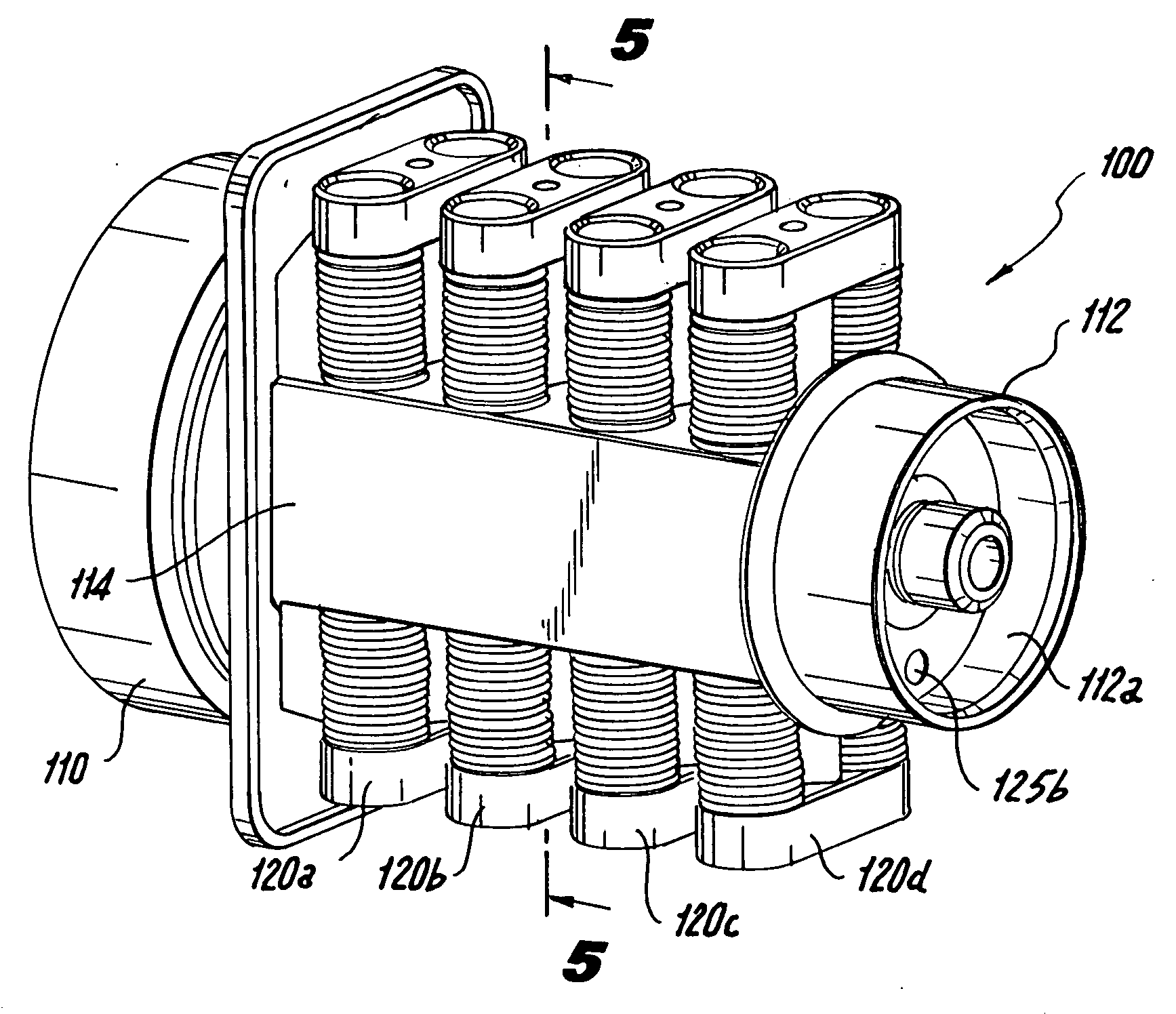
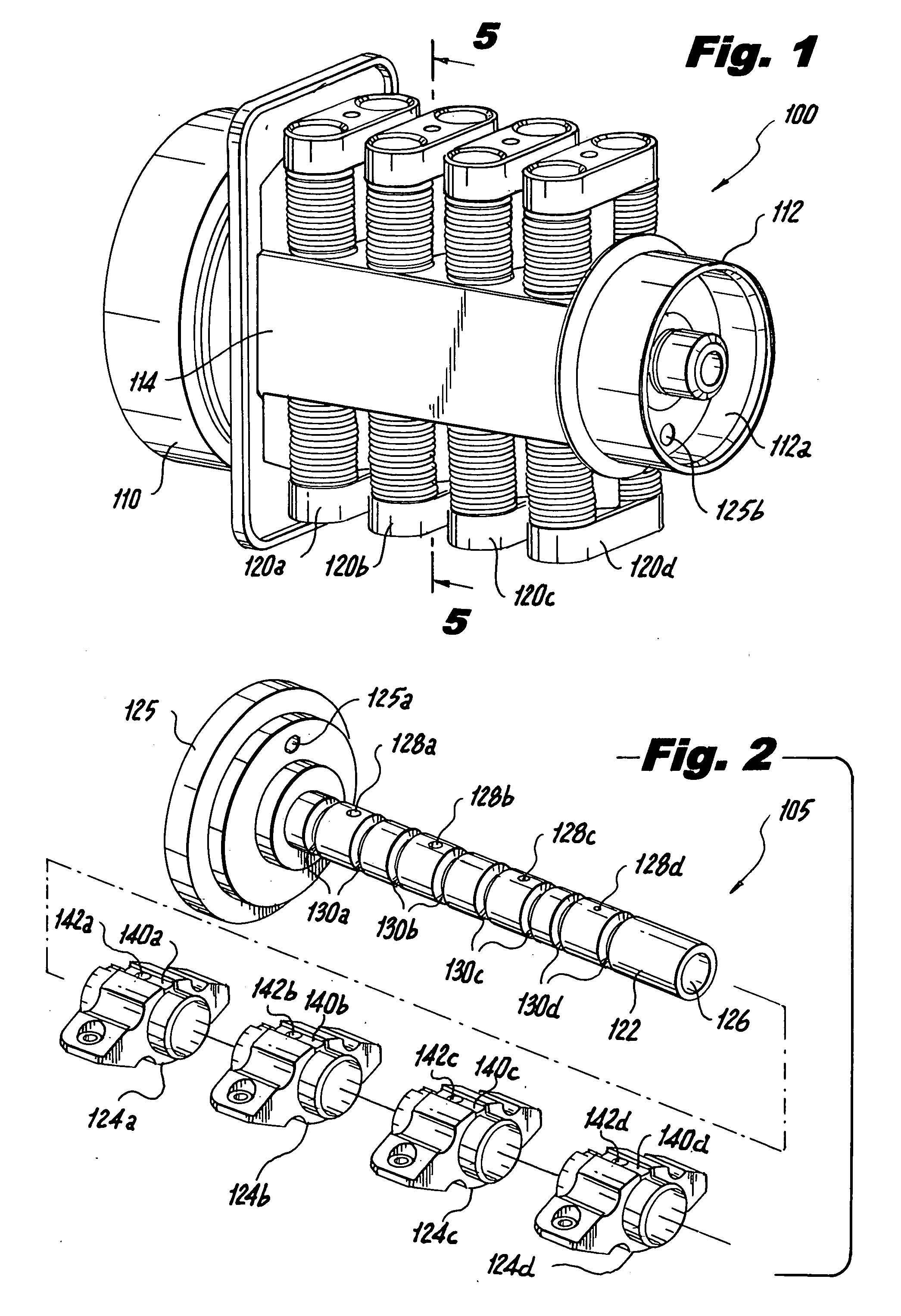
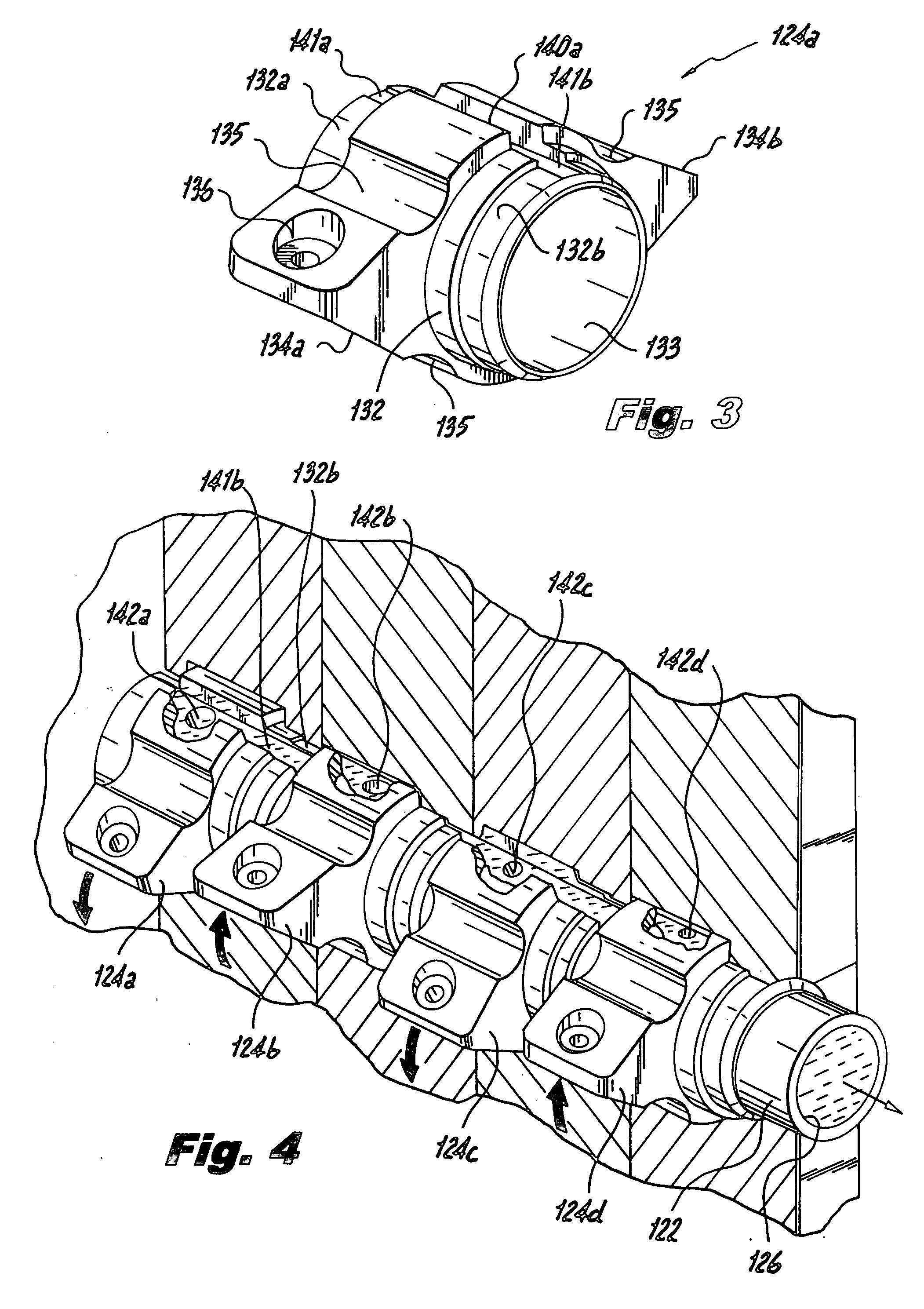
[0060] The latching oscillating valve assemblies disclosed herein are intended for use in conjunction with an active combustion control system. Preferably, the active combustion control system is designed to reduce localized thermo-acoustic combustion instabilities within the combustion chamber of a gas turbine engine. In such instances, the valve assemblies disclosed herein can be employed to pulsate or otherwise modulate fuel flow to individual fuel injectors at extremely high frequencies in excess of about 1000 Hz in proportion to detected combustion instability.

[0061] The active combustion control system is also intended to lower engine emissions, improve engine dynamics and maximize operating efficiency. In such instances, the valve assemblies of the subject invention can be employed to trim or otherwise actively adjust fuel flow to individual injectors to control the temperature pattern factor in a combustor and thereby reduce hot spots and other detected combustion condition...


PUM


Abstract

A valve assembly is disclosed for modulating the flow of fuel to a fuel nozzle at a high frequency or in a stepped manner to actively control combustion in a gas turbine engine which includes a valve housing defining an inlet portion for receiving fuel from a fuel source at an initial flow rate and an outlet portion for delivering fuel to a fuel nozzle at the initial flow rate or a modulated flow rate depending upon a detected combustion condition, and a mechanism disposed within the valve housing for modulating the flow rate of fuel to the outlet portion in response to a detected combustion condition.

Description

BACKGROUND OF THE INVENTION [0001] 1. Field of the Invention [0002] The subject invention is directed to gas turbine engines, and more particularly, to a valve assembly for modulating the flow of fuel to the combustor of a gas turbine engine for actively controlling the combustion process to maintain combustion stability and otherwise optimize engine performance. [0003] 2. Background of the Related Art [0004] Combustion instability is a significant problem in the design of low-emission, high performing combustion chambers for gas turbines. Combustion instability is generally understood as high amplitude pressure oscillations that occur as a result of the turbulent nature of the combustion process and the large volumetric energy release within the combustion chamber. Combustion instability diminishes engine system performance, and the vibrations resulting from pressure oscillations can damage hardware components, including the combustion chamber itself. Moreover, when the combustion ...

Claims


Application Information

Patent Timeline
Patent Type & Authority Applications(United States)
IPC IPC(8): F02C9/26
CPCF02C7/232F23N1/005F23N2035/14F23N2041/20F23N2035/18F23N2035/24F23N2035/16Y10T137/87314F23N2235/14F23N2235/18F23N2235/16F23N2235/24F23N2241/20
Inventor CORNWELL, MICHAEL D.BAXTER, RANDY C.FORST, MICHAELGOEKE, JERRY L.
Owner DELAVAN
Why Eureka
Try Eureka